When I put together the package of items that I would be ordering with the Tormach PCNC440 I probably made a mistake. I wanted a machine vice (vise if you over the Atlantic) and the recommended size for the 440 was a 4″. However a jaw set was not available with this size the same as it was with the 5″. After checking with Tormach I ordered the 5″ in the belief that it would be usable.
The 5″ is serious lump of metal and really only fits on the 440 table long ways on. The jaw set is really nice however. Sad to say that none of it has been used so far and if I am honest it is unlikely to be used. A large and heavy white elephant sits in the corner of the workshop. It is going to cost more to freight it back to swap out than is economic. Offers gratefully received !
What to do ? Looking around I found that Arc Eurotrade offer a range of machine vices. In particular I liked the look of the SG Iron Milling Vices as they have flexible jaw positions and had a ‘pull down’ action of the jaws on closing. They do not offer soft jaws but at a pinch these could be made as and when needed. I ordered a 100mm (4″) version and it is a nice piece of kit, seems solid, but not as heavy as the 5″ Tormach.
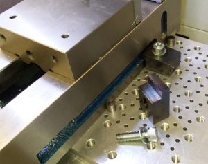
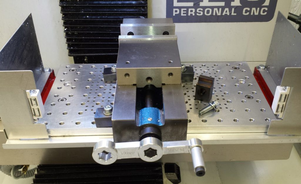
The vice did not come with any useful fixing clamps so what to do ? I had already made a tooling plate for the 440 table that has M8 holes on a 25mm matrix. The plate also has additional 4mm tooling pin holes within the XY limits of the spindle movement. The vice sits nicely between the M8 mounting holes and just needed some simple ‘L’ clamps to hold it down.
Designing and making the Clamps
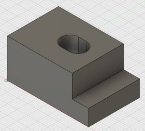
I designed something suitable on Fusion and did a 3D print of a prototype on the Sindoh 3DWOX to do a trial fit. This seemed to work fine so production of four metal ones was now needed.
A debate now ensued. Options at this point were : –
Use the Fusion model to CNC/CAM repeat produce four individual clamps which would need three set ups to face and cut.
Use Fusion to extend the model to have four clamps in one piece of stock to be cut to length as needed but machined using a full CNC program of all four on one piece of stock. Each clamp would still need facing after cutting
Use the single clamp already drawn in Fusion and use WCS increments to hop along the stock and create four separate clamps for cutting off as needed. Still would need facing after cutting.
Finally given their simplicity there was the option to run them on the Myford manual mill ….
Outcome
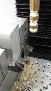
Well my hand goes up to say I funked it and made all four on the manual mill. I cut four pieces of stock (24mm x 19mm) to 40mm on the Kennedy hacksaw and faced the ends to length on the Myford mill. I jigged the Y position while sitting on parallels in the machine vice before cutting the clamping step on each. Next came an 8mm hole central in the slot before mill extending it out 2mm either side. Job done.
Would it have been faster on CNC ? I don’t really know. If I had drawn the ‘four in one bar’ version I think it would as there would have been only one setup apart from the facing off. If I had done the WCS based version of a single clamp then four set ups would have been needed, one for each WCS plus the facing. Either way both of CNC options would have increased my knowledge on CNC and I could have chalked another ‘result’ on the 440 fuselage mission tally board.
No excuses I know, but there is just something about manual milling and the intimacy of being in touch with the metal ……
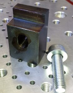
The finished clamping blocks were made to suffer heat and then an oil dunking to blacken them off to make them look almost professional.
So all of that was a bit of a ramble but you get the gist – CNC or manual.
Placement Tooling Pins
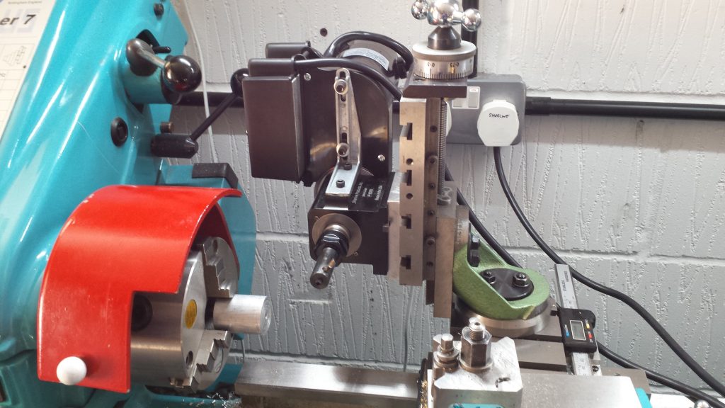
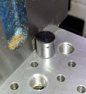
In closing the last thing I made was a couple of top hat tooling pins that sit in the tooling plate and align the vice position. This ensures the vice clamps can sit symmetrically either side of the vice. It makes for a quick set up if the vice has been off table. Note in the picture below the small piece of shim to get the alignment correct. (Lazy man syndrome creeping in again).
So the shop is now ready and better prepared to cut metal. Note also the NYC CNC training course produced vice handle being pressed into service on the new vice. Thanks to Kevin & John for that – was it nearly a year ago ???
Similar or related subjects : –
- Parting Off on the Lathe
- Workshop storage update using Spacemaster 5L boxes
- Plastic heat sealer – a useful workshop asset
- How to square up a scrap piece of stock ready for machining
- Deburring techniques in the home workshop
- First screw threads cut using Clough42 electronic leadscrew
- Machining a job that is outside a milling machine’s table travel using Fusion 360
- Stevenson Collet Block and the Angle of Dangle
- A Lazy Cable Clamp using 3D Printing
- Mill Turning Jig