Edge Technology Lathe Tool Setter

A useful tool for setting lathe tools on centre

There are many ways to set a tool centre line on a lathe. The most basic is just to trap a 6″ rule between the workpiece and the tool edge and adjust so the rule is vertical.

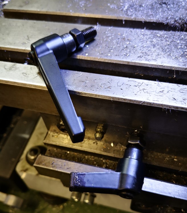
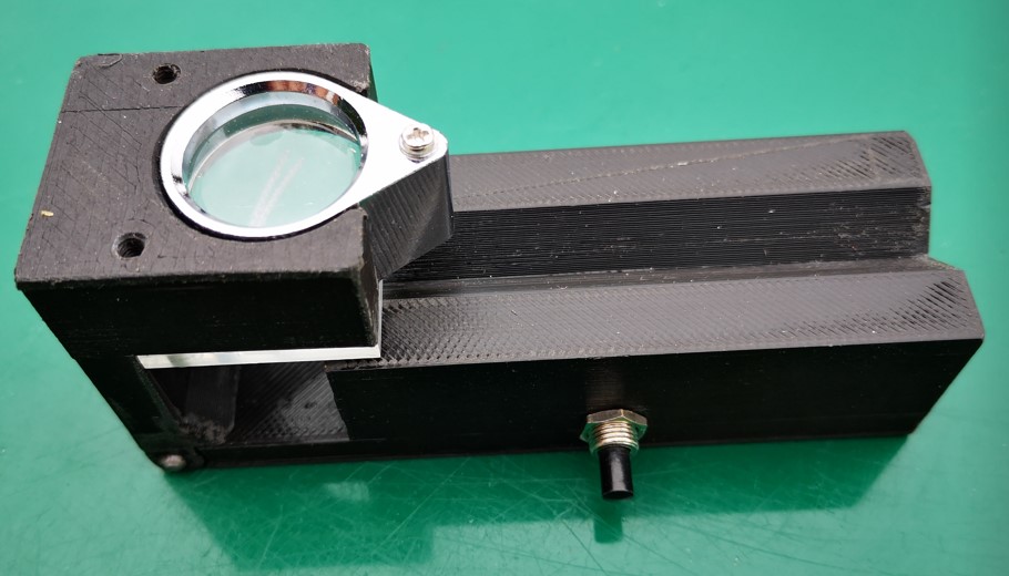
One gizmo I picked up at a trade show from the Machine DRO booth is this very useful tool by Edge Technology.

Edge Technology Lathe Tool Alignment jig

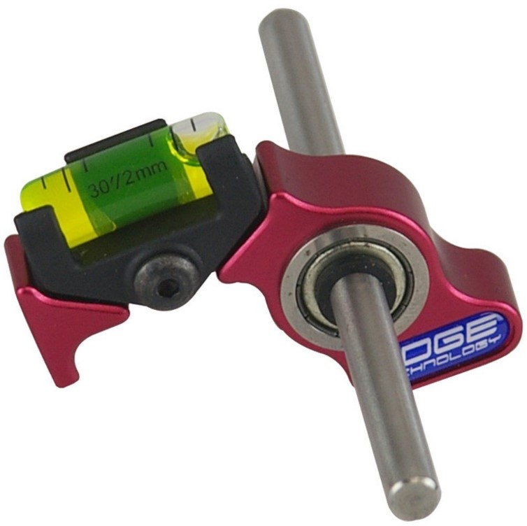
It is simple but clever. You mount the rod in the lathe chuck and then rest the bubble anvil on the tool edge. Edge Technology also do a more refined version with a calibrated scale.

It is not something that you use every day but every now and then I have a session with it and go through all my QCTP tooling and tweak them.

(If it has been one of those ‘not settling to anything’ days you can at least switch the workshop lights off with a warm glow that you did something useful …)

In the UK they are marketed by Machine DRO

(I have no affiliation to Machine DRO or any other manufacturer or supplier I might mention in my write ups but I will mention any nice pieces of kit I come across or use).

Links to similar or related post are listed below : –

Truncated Lock Levers

Restricted space modified lock levers

Each of the axis locks on my VMB mill uses two M8 cap head screws in association with a lock nut. This works OK if the hex driver is in reach …. but it never seemed to be …. so I decided to remove the cap head screws and fit lock levers instead. Lock levers come in male and female format and various thread sizes. The M8 versions all have 40 to 50mm long lever arms. This length doesn’t work comfortably in the space constraints on the VMB X and Y axis but is fine for the Z axis. Similarly I also had to reduce the length of the lever thread.

The obvious solution was to cut down the length of the lever arms. The trouble with this was the raw open end of the arm looked naff and did not sit easily with my usual perfectionist approach. The solution via Fusion 360 was to create some 3D printed end caps which I then bonded in place with Araldite. This finished the job properly.

Fusion 360 modelled end cap for the shortened lock lever arm open end

The Fusion 360 3D modelled end cap printed in under 4 minutes with a further 5 minutes for the Araldite to cure. I now have a much more elegant looking solution.

Full length lock lever and the truncated version with 3D printed end cap mounted on my VMB mill

All of which has led to a rethink the lock levers on my Quorn tool grinder. I get in a real mess with these clashing with each other. Where did I put the Araldite ? …..

Links to similar or related post are listed below : –

Gadget Builder Drill Point Inspector

A 3D Printed Version of John Moran’s Drill Point Inspector

John Moran has an excellent website that details all manner of engineering projects. He is a keen advocate of four facet sharpening of drill bits and he details a Drill Point Inspector device for checking grinding results. I quite liked the concept and thought it would also be a useful asset for checking the condition of milling tools. The design uses a small inspection eyeglass magnifier lens that can be flipped from end view to side on view for tool tip inspection.

Those who know me through my blog will know that I am of a lazy disposition which tends to cause me to step back and look for an easy way to manufacture something. John’s design immediately suggested to me that a conversion to a 3D printed equivalent would be a practical solution. I also picked up on a comment that John made that you needed good light to be able to view the drill point clearly. As a result of this comment, the 3D design evolved with the addition of a simple LED illuminator. I also added a ‘right angle stop’ so that when hinged for side viewing, the lens was held more repeatably.

Because the inspector will only be used now and then, I opted for two small hearing aid batteries as the LED power supply together with a single resistor and switch. I printed two slots in the cavity for a pair of nickel silver battery contacts to sit in.

View into the battery and switch cavity. The battery contacts are bent pieces of nickel silver or tinplate

The design was modelled using Fusion 360. The two parts of the body were 3D printed. The Perspex viewing graticule was CNC milled to size and the reference comparison lines were also engraved on the CNC. The inspection lens is available from many sources on EBay (x30 21mm). The inspection screen mounting holes are 3D modelled. Here are a couple of shots of the finished model.

3D Model of John Moran's Drill Point Inspector showing the model flat for end viewing of the tool
Model hinged flat for end viewing of the tool (the LED is just visible)
3D Model of John Moran's Drill Point Inspector showing the model hinged at right angles for side viewing of the tool
Model hinged up for side viewing of the tool

Note that the addition of the LED illuminator needs the modelling of a cavity on the bottom surface of the main body. When printing this part it will be necessary to have the printer provide support structures. I also printed a cover for the cavity but this could be an offcut from an old credit card or similar thin plastic sheet.

Once printed I found the parts needed slight ‘fettling’ to remove any surface striations on the V block section, in and around the hinge section and around the eyeglass mounting slot. That aside it printed fine and the parts went together easily. More to the point it works well and is a useful tool to have to hand.

The Fusion 360 file and STEP files for the main two model parts are available in the following ZIP file. If you need additional information please get in touch.

Links to similar or related post are listed below : –

Rotating Baseplate for BK3 Bandsaw

Lazy Susan Does Something Useful

I was watching a YouTube video of the renovation of a BK2 bandsaw which appeared to have a rotating baseplate. (I have to say I was not sure if it was a fixture on the BK2 or just a video accessory to allow easy rotational viewing). That aside the idea struck home as my BK3 Bandsaw is squeezed in on a bench and often I have to physically rotate it to accommodate the size and shape of the material being cut.

The hot weather we are currently experiencing meant the barbeque and patio furniture were both getting well used. Our circular patio table has a central hole for the parasol and round this hole is a Lazy Susan ball race. This has a glass ring that rests on top which allows the various delicacies my wife provides (to mask my charcoal blackened offerings) to be easily rotated and accessed by all sitting round the table. The Lazy Susan ball race ring looked like a good candidate for the BK3 rotating base.

Checking on Amazon you can buy the rings in various diameters and from various sources. The 8″ version sits neatly inside the BK3 flanged baseplate but some careful thought was needed as to how this could be mounted on a wooden baseplate. The solution was to use M5 countersink screws to mount the inner ring to the underside of the baseplate and to use M6 screws to mount the outer ring to the wooden baseplate.

Here is a brief run down of how to implement this idea.

Remove the white bungs that come fitted to the rings and mark, drill and tap (M5) the inner ring holes into the BK3 baseplate. I mounted the ring centrally within the cavity. If you are worried about your accuracy then once the baseplate is marked and drilled, you can open up the inner ring holes to say 5.5mm.

Bottom View with the Lazy Susan ring in place

Tap the holes in the outer ring M6. These are already 5mm clearance so they can be tapped without drilling out.

Cut the baseboard to size. This can be rectangular or circular and from whatever material you have to hand. Offer the ring to the baseboard so it sits centrally and spot through the four M6 tapped holes. Drill these through at 6.5mm and countersink the lower side. Note that in theory you could do away with the wooden baseboard but the BK3 then tends to tip forward when you press on the BK3 cutting table.

Assembly is a juggling act. The two rings need to be spaced off from the BK3 baseplate and from the new baseboard. I used M6 nuts over the M5 screws as the spacers for the inner ring. I used a single M6 washer on each screw to space off outer ring on the baseboard. Fitting these washer is the main juggling act. To make life easier I dab glued the washers in place on the inside face of the baseboard. Here is a simple sketch of the construction.

That completes what is a simple modification using a Lazy Susan ring and from my point of view it dramatically adds to the usability of the BK3.

BK3 with rotating baseplate

I have added this modification to my compendium write up of my BK3 modifications. The new version 3 can be downloaded on this link.

Links to similar or related post are listed below : –

Femi NG120ABS bandsaw failure and support from Stakesy’s

Last week we had the hottest day in the year so far and I had a couple of jobs to complete in the workshop.   Not ideal but with the doors open I had a little through breeze.   I had lots of aluminium to chop to length and my Femi NG120 bandsaw was doing sterling service.

A few days later when I needed to use the Femi again it was dead.  Not a spark of life.   I buzzed out the electrics and the trigger switch, emergency stop and end of cut switches were all working fine.   

My conclusion was the motor controller had failed.   This is a potted electronic assembly that sits on the end of the motor assembly inside the top of the motor housing. I measured various voltages with and without the trigger switch in action and sent the details off to Stakesy’s who is the UK distributor of Femi (the saws are made in Italy).   As bad luck would have it my bandsaw was a few months outside of a 12 month warranty.

Stakesy’s sent off the details to Femi and after some email interchanges Femi agreed to supply a new motor controller module free of charge.   This arrived in the post a few days later.   It was an easy fit, just four wires into a chocolate block and the bandsaw sprung back into life.   My hacksawing arm muscles breathed a sigh of relief. 

As mentioned earlier,  the motor controller module is a plastic moulding that has the electronics potted into the moulding.   There are some parts proud of the potting compound but in the main all is submerged.   With hindsight I wonder if something failed with the high ambient heat it was subjected to on my hottest day activity.

Femi motor controller module

Great service from both Stakesy’s and Femi.   A big thank you to Matt and Alex for getting my NG120 up and running again.

Similar or related subjects : –

Verified by ExactMetrics