Simplify3D has just released version 5 of their 3D printing slicer program. Simplify3D is a subscription program and is unlike Cura and Prusa which are both free. There is a special price for the upgrade if you are updating to the new version. I had been running the previous version of S3D and fully expected to be able to upgrade and use the same driver file (.fff) for my Qidi i-fast. Not so …. despite S3D saying my printer was compatible etc etc.
I sent a message to Qidi support and next day had a reply giving details of edits to the start and finish GCode routines. They also sent me a new .fff file that had been issued by S3D so clearly others had contact S3D with the the same problem. To be clear I am not saying S3D are not responsive. I just expected that they would check out these issues before issuing a major upgrade. Five Stars to Qidi though who as always are red hot on support.
Attached below the upgrade details as received in a ZIP file. Note that I am currently travelling so I have not had chance to check out the changes …. proceed with caution !
I came across the design of a Gack machine vice on a metalworking forum. This is a two part vice that picks up on the tee slots in a mill table to allow an infinitely variable clamping width within the limits of the table dimensions. It is ideal if a part needs to be skimmed flat over a wide area. The item to be machined is clamped by an adjustable jaw against a fixed jaw and is supported by parallels as needed.
The grip tightening adjustment is done with a ball bearing pushing centrally on the adjustable jaw with a M10 cap head screw and the gripping jaw hinges downwards on two dog point grub screws. Here is an image of my interpretation of the concept. My aim was to create a vice that would be able to be mounted on my M8 tooling plate which has holes on a 25mm matrix or directly on the milling table tee slots which are spaced at 50mm.
I modelled my version in Fusion 360 and below is the Fusion exploded view.
The metal side plates are to increase the strength of the two hinging pivots of the clamping jaw.
The idea works well for light skimming jobs but would not be suitable for large depths of cut.
If you want a really robust version then you could replace the PLA print with a metal equivalent or you could buy a kit from Hemmingway Kits but their castings restrict the use to tee slot mounting only.
UPDATE: – Since the original post I have updated the design to a totally metal version. The static jaw is now much easier to fabricate using a piece of angle plate. The mounting slot dimensions are specific to my M8 x 25mm matrix tooling plates.
Links to similar or related post are listed below : –
This modification has worked very well … except when I want to use the height gauge off line when the PathPilot computer isn’t switched on. The level of frustration over the downside impact of this well intentioned modification was starting to irritate.
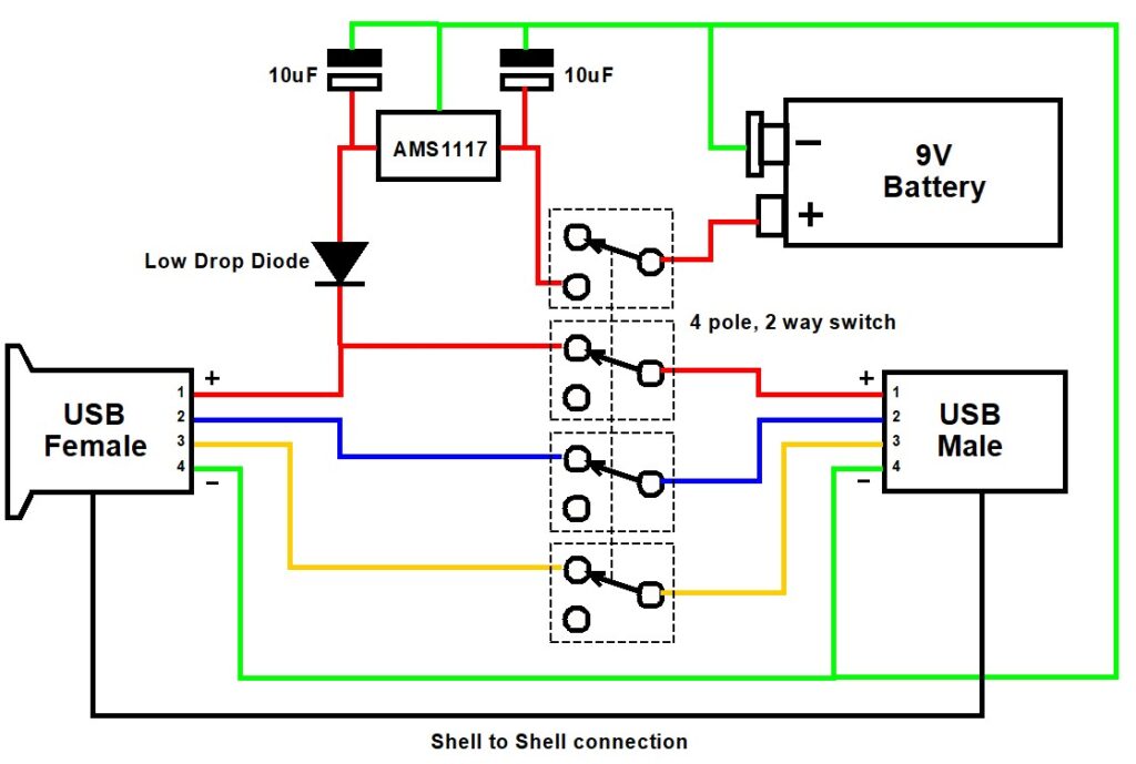
I had a male and female USB socket in stock along with a 4 pole 3 way rotary switch and a few AMS1117 low drop out 5V regulators. The rotary switch was one of those where you can move a selector pin to make it a 4 pole 2 way. A quick sketch and I think the problem is solved.
The logic is quite simple. Note that the colours used are just to make the diagram more easily understood and the colours chosen have no bearing on normal USB cabling colours.
In computer mode the wiring acts as a pass through connection for normal USB working. The computer is connected to the USB Male and the height gauge to the USB Female.
In ‘local’ mode the USB connections from the computer are all disconnected by the switch and power to the height gauge is provided instead by the 9V battery via the AMS1117 5V regulator and the isolating diode. Note the diode needs to be a low forward voltage device such as Schottky diode. It is not super critical as the regulator I fitted to the height gauge electronics box is a low voltage drop regulator. In total the current drawn in ‘local’ mode is around 10mA so the 9V battery will last a long time …. providing I don’t forget to switch it off (i.e. that is back to ‘computer’ mode). Which probably means I should fit a LED to the output of the AMS1117 to show the device is live on battery……
I built the device as a bird’s nest and 3D printed an enclosure. One less workshop frustration (hopefully).
One other thing to mention. The original write up detailed adding a 3V3 AMS1117 low drop out regulator to power the height gauge. See the link below.
If it is cold in the workshop the display on the height gauge can be a little dim to read. I have boosted the contrast by ‘jacking up’ the AMS1117 in the height gauge electronics box by adding a single Schottky low drop diode in the ground lead of the regulator. This increases the output voltage by the amount of the forward drop of the diode. To be clinical you should really add a tantalum capacitor across the diode to improve the stability of this modification.
Links to similar or related post are listed below : –
My blog post about installing a Chinese RV diesel heater in my workshop is probably the most popular post visited on my blog. This has been even more so with the present cost of fuel and the onset of winter weather. You can read my original post here and I suggest you read that post first of all to make more sense of what follows.
First let me say that installing the heater was one of the best workshop improvements I ever made. The heater performs very well and quickly gets my working area up to temperature. My opinion needs a bit more defining.
My workshop is contained in what should be the house garage and is roughly 6m x 4m x 2.5m. It is built onto the side of the house and has one outside wall which is an unfilled standard brick cavity. I have covered the garage door with 1″ Cellotex equivalent foam boarding. This was convenient to mount to match the door construction and probably the thickest I could use without impacting on the garage door operation. My wife has provided a door bottom ‘sausage’ muffler filled with polystyrene beads. The door is therefore relatively draft proof but not perfect.
The roof over the workshop is double skin plasterboard and has timber joists with 6″ of fibre wool insulation.
With the current overnight temperatures (-4C) the temperature in the workshop drops to around 15C. The heater is a 5kW branded model but likely to be only 3kW in practice. It takes around 1 hour to get the temperature up to 19 to 20C in the present externally very cold conditions.
Fuel – I use an approximate mix of domestic heating oil (40%) and vehicle diesel (60%). Why do I do this apart from cost saving ? I have read that domestic heating oil does not have sufficient lubrication content to lubricate the demand pump action in the heater. I therefore err on the conservative side and use a mix of the two. I have no idea whether this is fact or fiction. I do not have access to red (Agri) diesel so this is not an option for me to use but clearly would be the cheapest route and would provide the necessary pump lubrication.
I have a 20 litre diesel storage can which I fill at the local garage every 2 or 3 weeks. This is eyeball mix tipped into the heater internal 5 litre tank together with the heating oil which I siphon out of our domestic tank as needed. I would estimate that I use 5 litres of the mix every 3 to 4 days depending on outside temperatures and based on at least an 8 hour day ‘making things to make things’ as my wife calls it. If the heater tank runs dry I find I do not have to re-prime the heater pump but simply refill the tank and switch back on.
The heater controller is the second one I have fitted. The display died on the first one. The controller is easy to use and allows timed operation, set temperatures and live temperature readouts. It is a three wire connection and I had to extend the cable length with a spliced in 3 core section. The OK button cycles round the various display readings and the ON/OFF symbolled button is the lower middle button. The heater needs a single very short press to start the heater up and a longer press to shut it down. Over pressing the ‘start’ leads to an abortive shut down procedure. The left and right arrows increment the various settings selected by the OK button.
The start up current is very high, around 10A at 12V. The choice of power supply is therefore important to be able to sustain this surge. The controller display allows the value of the supply voltage to be checked. The heater once started roars away at full pump speed (a very fast clacking noise) and once at the temperature set point the clicking drops down to a slow tick. There is an icon on the display that mimics the tick. The sound from the ticking is conducted into the workshop via the inlet and outlet air ducts. Like the ticking of a clock, you just get used to it and mentally cancel it out. Both the roaring at switch on and the ticking are louder outside the workshop than inside but these do abate once the heater reaches the set temperature. I am conscious that both the roar and the tick are probably audible with the neighbours but their ground source heat pump is equally audible to us.
The shut down procedure after the long press on the controller button initiates a full bore roar from the heater. I assume this is to burn off accumulated soot in the heater from the slow background tick reached at temperature set point.
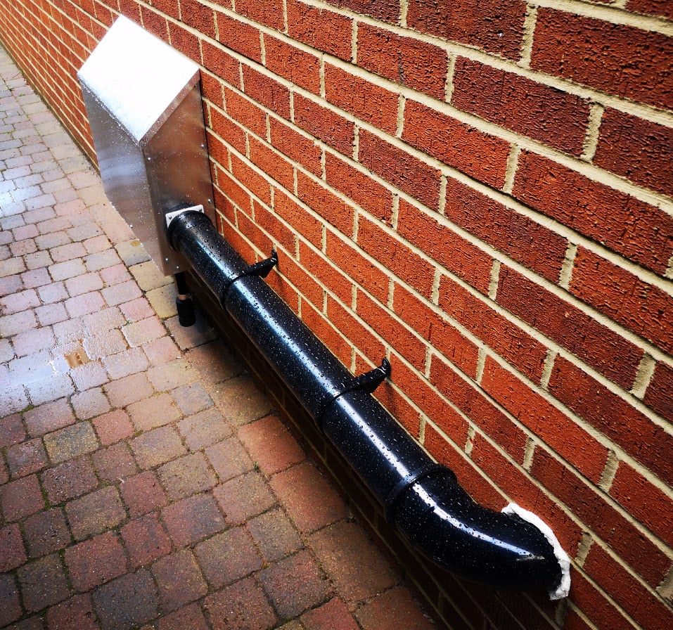
As mentioned above the exhaust is noisy. I believe that the choice of silencer affects this. Straight through ones are to be avoided. There is also some discussion about having two in series to reduce the noise further. I have not tried this. Note also that the exhaust does create black soot so I have fitted an aluminium sheet on the wall to protect the brickwork. Standard shower cleaner spray with a bleach content does remove this. The soot plate can be seen in the image below along with the 20 litre top up container.
My prior post about how I installed the heater details the inlet and outlet duct locations. The heat outlet grill is on the workshop wall between my two milling machines. This is not ideal but was the only practical location. The return is under the Myford stand.
The heat outlet has the shortest duct run being almost directly at right angles through the wall from the heater burner outlet. The return duct is located under my Myford lathe stand and is a simply constructed wide mouth housing tapering down to the flexible duct that connects back to the well insulated ducting along the outside wall to the heater. I have fitted a fine gauze mesh over the mouth of the taper to stop debris entering the heater. The image below gives some idea of the construction to fit the available gap under the Myford.
I think I have covered most of the questions asked by readers but feel free to contact me if you need to know anything further. Clearly everyone’s setup is different but for my workshop this is an outstanding and relatively low cost comfort benefit. It also creates dry recirculating air that benefits my equipment.
Links to similar or related post are listed below : –
A good reason why not to leave a parallel on the way cover
I was running a milling job on my 440 the other day and I had left a parallel on the Y axis front way cover when I had switched off in the evening. Next morning I switched on and homed the axis in the usual order of X axis and then the Y only to hear a crunch as it reached the homing position. The parallel had got jammed under the table front shroud. I reversed the motion, removed the parallel, homed Z and carried on.
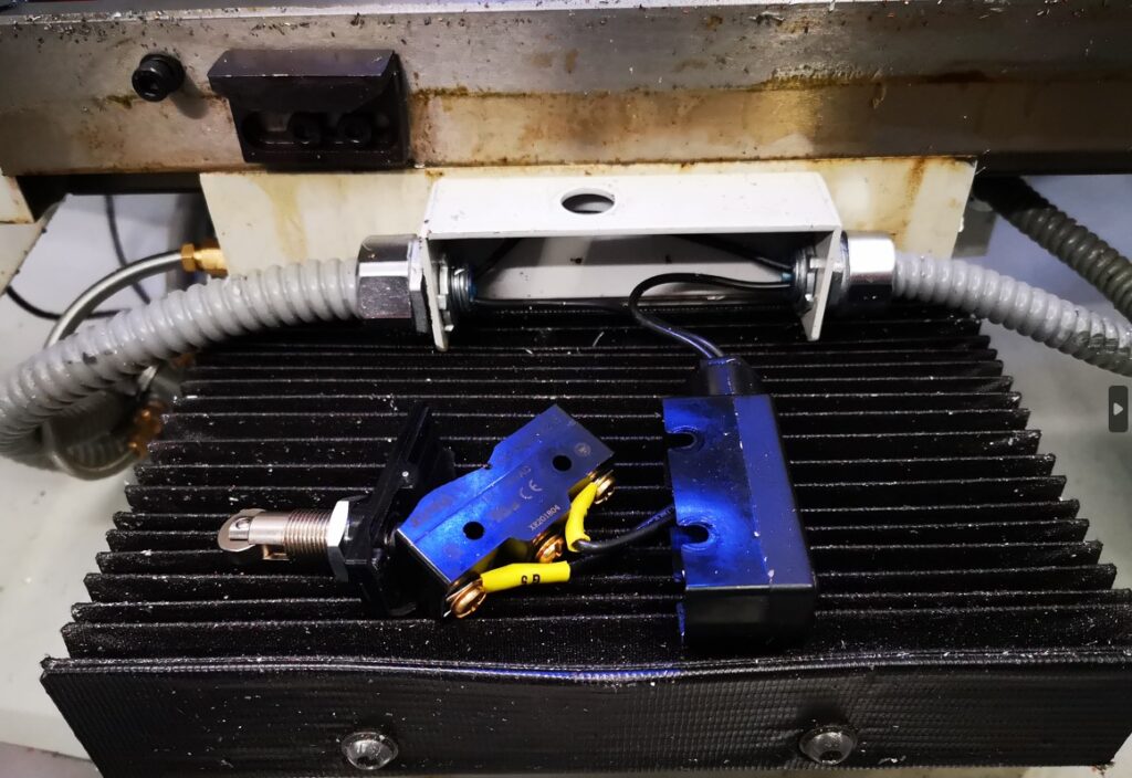
Fast forward to the next day. Switched on and homed X which resulted in a very bad end stop stepper chatter. I stopped the motion and moved the X axis back. Something bad had happened. I stripped off my machine vice and my tooling table and removed the table front cover. The limit switch had been crushed, presumably by the parallel the previous day.
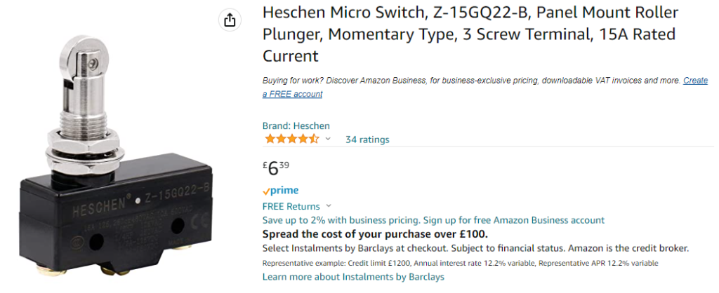
I’d like to say that this is the first time this has happened …. but it isn’t. (Hence the ding in the cover front edge …). A quick check on Amazon revealed quite a few identical looking replacement switches. There was also a twin pack available from China for much the same price but clearly much longer delivery time. A new switch was ordered and all is now up and running again (after re-tramming the tooling plate and then the mill vice etc etc …. what a pain ….)
In passing I do keep pondering the 440 limit switches and wondering if I could replace them with inductive sensors but it all looks a bit difficult having to sort out the additional wiring needed. Maybe another day ? (Sadly such a modification would still not stop me stupidly leaving things on the way cover ….)
Links to similar or related post are listed below : –