Plastic heat sealer – a useful workshop asset

Clough42 has just posted making a protective cover for his plasma cutter control screen.   As ever with James it is engineering perfection with stitched corners.

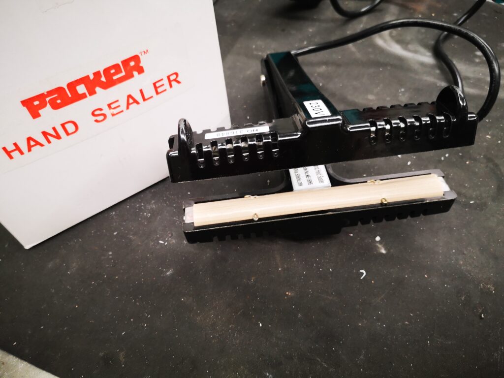
My lazy way (as ever) is to make such items using polythene plastic sheeting and a heat sealer. 

This allows me to quickly make bespoke covers and pockets for all manner of applications.  Here are a few examples.

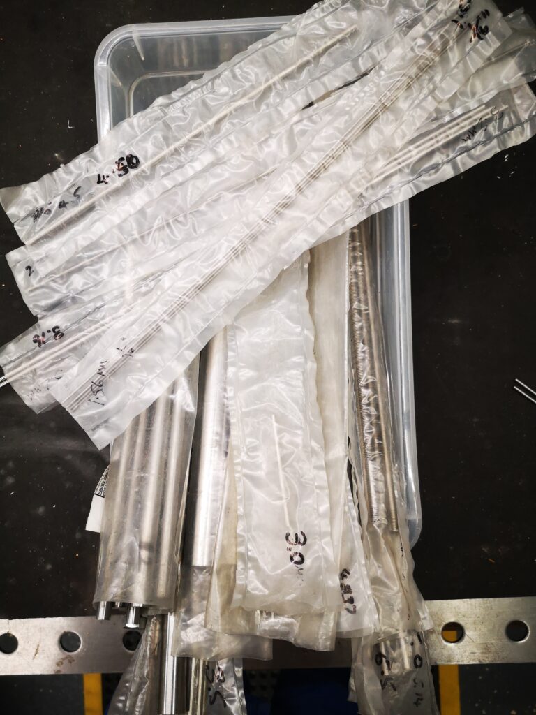
All my silver steel is stored in such pockets and has the size written on the sleeve using a Sharpie. 


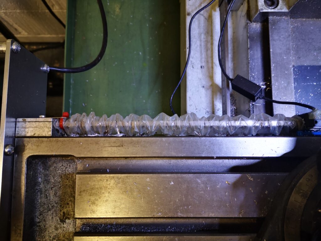
The rear DRO scale on my VMB has an open ended pocket either side of the vice that acts as a concertina cover to keep cutting oil from affecting the scale reader.

So another useful tool to have available (without having to thread a needle).

Similar or related subjects : –

Dewpoint alarm monitor to help avoid rust issues in the workshop

A Dewpoint Monitor to protect the workshop

I have recently read a number of posts on workshop forums about rust degrading workshop assets.   When the temperature of the air reaches close to the dew point then the moisture in the air will condense on the cold surfaces in the workshop and moisture will inevitably lead to rust forming.

You can protect against this to some extent by ensuring that all exposed surfaces are coated with lubricant of some sort such as WD40 and only dry sources of heat are used in the workshop.   A better protection solution which was popularised by the clockmaker William Smith, is make a 50/50 mix of linseed oil and thinners and coat this on the objects needing protection.  This works well but does not last forever.

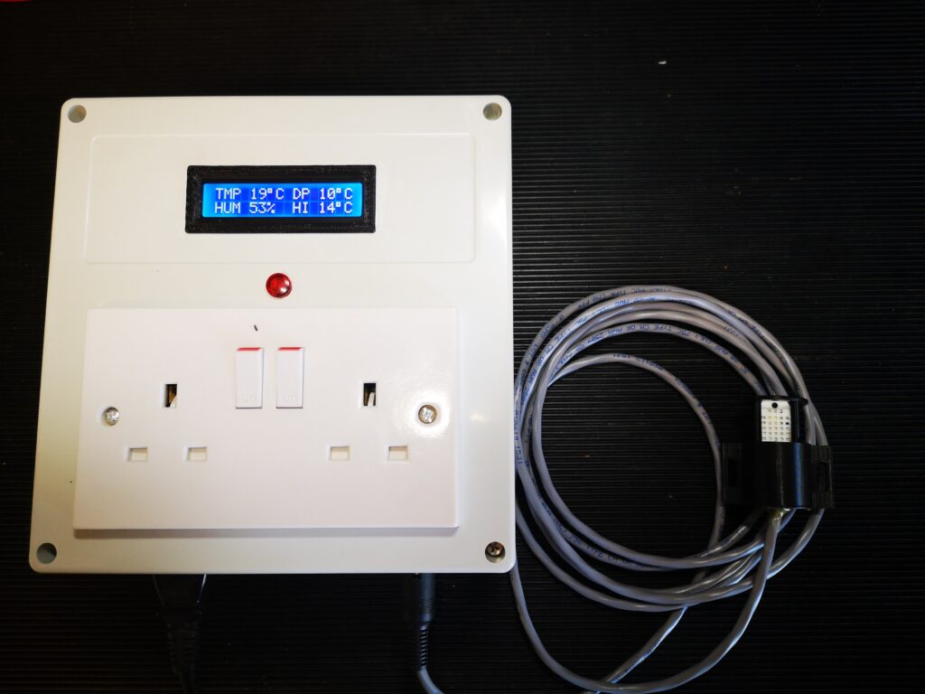
Looking around on the internet there are various Arduino projects to create a dewpoint monitor using the DTH11/DTH22 which are combined temperature and moisture probes.  Such devices, with a little bit of maths, can provide an alarm output if the dewpoint reaches close to the air temperature.   This could be used to turn on a heater and raise the air temperature and avoid moisture being deposited.  I opted to have the sensor remote via a cabled connection.

The dew point calculation I used is the Magnus-Tetens formula (Sonntag90).  This provides accurate results (with an uncertainty of 0.35°C) for temperatures ranging from -45°C to 60°C.

The dew point is calculated according to the following formula:

Ts = (bα(T,RH)) / (a – α(T,RH))

where:

Ts is the dew point;
T is the temperature;
RH is the relative humidity of the air;
a and b are coefficients.

The Sonntag90 constant values are : – –

a = 17.62 and b = 243.12°C;

and this is the final formula needed : –

α(T,RH) = ln(RH/100) + aT/(b+T).

I made a prototype using an Arduino Pro Mini as the controller and I used the above equation to calculate the dewpoint from the humidity and temperature readings input to the Arduino from the DTH22 sensor.   Once the dewpoint reaches within a defined limit of the temperature, a relay is closed to allow heaters to be turned on.   This trip point also causes the LCD display flash to warn that a trip point has been reached.

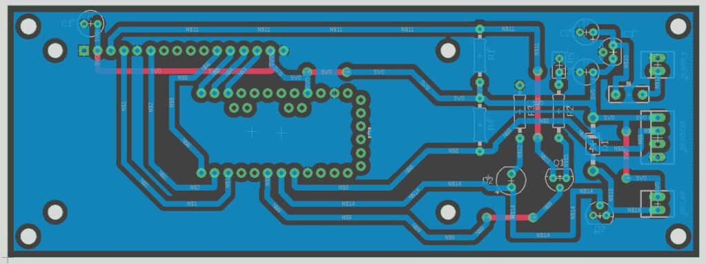
The working circuit was drawn in Fusion Electrical and a printed circuit board layout was created.   Fusion’s Electrical CAM output as Gerber and Epsilon files were converted in FlatCAM to CNC GCode.  The CNC files were than posted to my Tormach PCNC440 to mill the copper traces.

I designed the PCB using through hole components to make assembly easier for my more mature eyesight.

The trigger output from the PCB can feed any 5V coil relay that is rated with contacts capable of feeding the AC voltage and current needed for the heaters.

UPDATE 18/12/2021

Due to demand I have ordered a small quantity of offshore manufactured PCBs for the Dewpoint Monitor.  If you are interested in one then send me an email as per address below.  First come first serve.

UPDATE 1/11/2022

Auto reset code added should the sensor lose connectivity,

New write up is below including the new code

Similar or related subjects : –


Engineering Video Favourites Updated List

As the months (and years !) have passed while authoring this site, my favourite YouTube sites have morphed and changed as my skill level and interests have become more focussed.   The other aspect is that many of my early favourites have just faded away and now rarely post if at all.  I guess it takes a great deal of commitment to create regular footage over a long period of time so it is understandable that people come and go.

At the risk of everyone clicking and leaving, here is a share of the sites I now look forward to visiting and viewing : –

Top of the list is Clough42 for his highly professional, regular posts on home workshop activity but key for me is his use of Fusion 360 for all his engineering modelling.

I met Jimmy Diresta at NYC CNC in 2016 and I love to watch his almost ‘off the cuff’ creations in metal and wood.

For TIG welding I have watched many sources but Pacific Arc TIG Welding is my current favourite and Dusty does some amazing stainless TIG welding artworks.

I need to mention This Old Tony even though he has been absent from the scene for a long period.  He is now back and on top form.

Then of course for serious CNC activity there is John Saunders and John Grimsmo.  Both these guys have done incredibly well as they have emerged from their garages and blossomed into YouTube stars.

Finally a less well know site for Fusion 360 is Mechanical Advantage hosted by Kevin who was my instructor on the NYC CNC Fusion 360 course.  Really nice guy and always helpful if you have a problem.

So that is my current short list of ‘ones to watch’.   If you haven’t discovered any of them then check them out.   But don’t forget to come back here every now and then just in case I get up to something interesting.

Similar or related subjects : –

Fusion 360 Electrical Personal Library tip

Custom Library in Fusion 360 Electrical module

PCB layout created in Fusion 360 Electrical module

My knowledge in the use of the Fusion 360 Electrical module improves by the day as I use it more.  Not having used a PCB design package before I don’t have anything to compare it to so I can’t be objective in any comments.

One thing that does frustrate me is the Library of parts.   Everything is wonderful if the part I want use is available already created but if it isn’t readily to hand then a work around is needed.   First call is to use a similar package part and edit the Value.  Second option is to use Mouser’s Library Loader which seems to work well …. providing they have the part available.  Last resort is to try to create a new part.   I have done this a few times but not enough to make it an automatic process and hence frustration still reigns.

The other issue with using Libraries is that I am slowly building up a physical stock of my preferred parts.   It becomes frustrating when beginning a new design using my preferred parts, trying to remember which available standard library I had selected them from.  I recently stumbled upon the EXPLIB command line macro.   This allows you to create a unique new library of just the parts used in a particular design.  So now I can easily find the part I used in Design X to be able to use it in my new Design Y. 

Progress indeed.

Onwards and upwards.

Similar or related subjects : –

Adding thrust bearings to the Myford Super 7 with Clough42 ELS fitted

Some time ago I documented my implementation of the Clough42 Electronic Leadscrew on my Myford Super 7 Big Bore lathe.   I also wrote up adding thrust bearings to the top slide and cross slide adjusters.   What remained outstanding was adding thrust bearings to the leadscrew.  While there is a commercial kit from Hemmingway Kits to install these, my implementation of the ELS involved a direct drive to the leadscrew at the tailstock end of the bed and made things difficult – I ran out of length on the leadscrew.

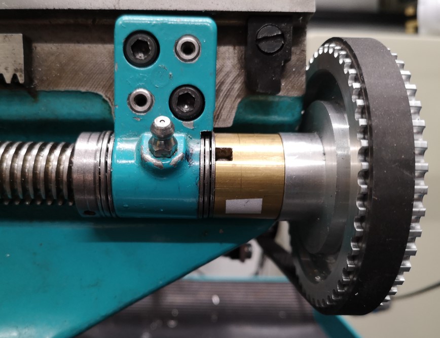
After considering the situation I opted to retain my ELS drive concept and gain space for the bearings by shaving metal from the Myford leadscrew bracket.  It is not an ideal modification as I am always very reticent about physically changing the structure of my machines.   Despite this I have to say it seems to have paid off and I now have a very stable and repeatable leadscrew feed from the ELS.  Here is a photo of the result.

modification to the leadscrew mounting for adding thrust bearings
The final assembly using the ELS drive concept to the end of the leadscrew and how space was made for thrust bearings to be fitted

I have added details of the modification to the original thrust bearing write up and this can be downloaded as a PDF from the link below.

Myford Super 7 Thrust Bearing Mods including leadscrew

Similar or related subjects : –

Verified by ExactMetrics