3D Thin Wall Printing Experiences

Probably An Inconclusive Ramble

Some while ago I was asked to 3D print the component parts of a 1200mm wingspan glider. The design STL files are available as a paid download from the SoarKraft website.

The first problem this created was that my Sindoh 3DWOX had insufficient Z height for the 200mm high print sections. This was a thinly disguised excuse to upgrade my 3D printer to a Qidi ifast. This has proved to be a good decision and I am very impressed by the Qidi and the quality of the print results that it generally produces.

I now need to qualify that statement because I have struggled (and also learned a lot) trying to print thin wall prints for the glider parts.

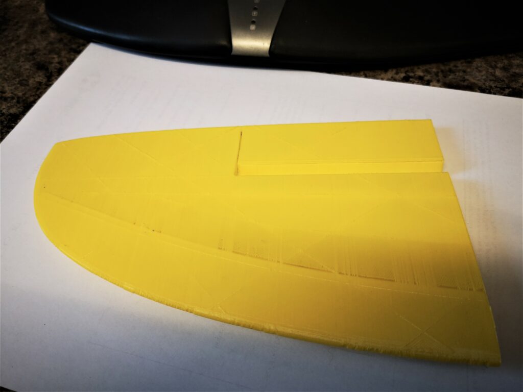
The Qidi comes with a slicer that is a skinned version of Cura. I struggled to get good thin wall results. The main problem being transparency effects in the printed surfaces immediately following internal bulkheads within the wing design. I mentally envisaged this as the extruder being unable to start pumping filament fast enough following the bulkhead transition. You can see this along the inner curved line on the image below. There are very fine threads of PLA bridging the gaps.

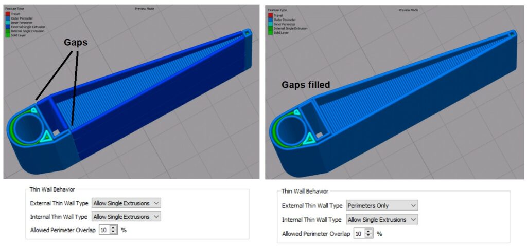
I am also a subscriber to Simplify3D. Their website has a help article on Thin Wall printing and a recommendation that the Thin Wall Behaviour can be improved under the Advanced/Thin Wall Behaviour by selecting Allow Single Wall Extrusions for both internal and external walls. Playing with these options led to good prints that met the SoarKraft recommended weight. I need to do more investigation on the other options in the two Thin Wall drop down boxes but here is an image of two examples.

I asked Qidi if there was a similar fix in their slicer. They sent me a revised config file that did fix the problem but led to a significant increase in weight on the finished print.

The problem has also been beneficial in making me realise how important the slicer simulation was as a tool (as can be seen above). It allows you to see what is likely to happen with each change to the configuration print settings. Obvious but not always investigated.

The other discovery was that neither slicer (Qidi or S3D) are able to import STEP files which does seem a bit strange. STEP files are more accurate than STL files and STEPs are easier to modify in CAD programmes.

Sorry this is not a radical post but does show that 3D printing is not just ‘click and go’. The other comment is that there are so many options to change in a slicer config that I don’t think I will every get to grips with their individual impact on the print.

Links to similar or related post are listed below : –

Parting Off on the Lathe

That old Chestnut …. Again

Go onto any home workshop forum and I am sure you will find a number of threads on the fractious subject of parting off on the lathe. It is a perennial topic that everyone has their sometimes not so humble opinions on. It seems to be the machinists equivalent to the search for the Holy Grail.

If you have a bulky rock stable mass for your lathe the problem is easier to solve. Rigidity rules when it comes to parting off. If you are less privileged on funds or workshop space you are more likely to have a Myford equivalent machine. The problem will then get magnified simply because there is not so much stability in the machine structure.

I have tried various parting tool configurations and I have to be honest I get a severe case of ‘squeaky bum time’ when faced with parting off steel. Brass and ally I can cope with but steel usually makes me wimp out and rush for the hacksaw.

My parting weapon of choice is a hand graver. This is appropriate for small diameters and using a graver is very educational. You can feel how the cut is progressing and you can feel how the cutting action changes as you change the angle of attack. It is a lovely craftsman’s tool and for clockmaking, in various geometries, is indispensable.

For larger diameter parting I have progressed through HSS front cutting, insert front cutting, Hemmingway kit rear cutting and now the latest variant – a simple insert tool holder rear cutting.

My parting collection – graver, HSS, front insert, Hemmingway and the new rear insert

To be fair the insert front cutting does work for brass and ally but on claggy ally the tool would often dig in and can jam the chuck no matter how much lubrication I use. This I assume is because front cutting leads to a digging in action whereas rear cutting throws the tool outward from the cutting groove.

The Hemmingway kit was a thoroughly enjoyable experience to build and it looks brilliant but the blades seem too prone to flexing. It is a real shame given how nice the finished tool looks. (Yes, I do accept that it might be something to do with my construction). So nice as it looks I tend to have little universal confidence in it.

So what is my latest parting panacea ?

I have mounted a standard, universally available, insert blade parting tool (SPB326) on the side of an old rear mounting post that originally came as part of a knurling tool. The tool clamping on the post has a sliding curved pressure support surface which allows tool height variations. I fixed a 12mm square steel clamping block on the rear of the parting blade with 2 x M5 cap head screws and clamped this in the mounting post.

I did a few facing actions on some brass to get the centre line correct and then began trial partings on brass and ally. It worked like a dream. Encouraged by this I moved onto a piece of 10mm silver steel (drill rod). Plenty of cutting oil was applied and apart from the initial engagement chatter it just cut beautifully. Lovely snails of swarf, no SBT reaction, no hacksaw needed.

Alright the blade and the insert are wider than ideal (3mm SP300) but this probably adds to the rigidity of the setup. A consequence will be that I will be wasting more metal in the cutting action but at last I seem to have a tool and recipe that I trust to work.

Well, for the time being anyway.

Links to similar or related post are listed below : –

Adding Colour Coding to Fusion 360 Assemblies

How did I not know about this Fusion 360 facility ?

I was watching a YouTube video on Fusion 360 joints by Garin Gardiner. I couldn’t help but notice that he had colours on his assembly listing and time line. My interest was really perked…..

A quick search revealed that this is a standard but maybe not so obvious Fusion 360 feature. Go to the Inspect drop down menu and then Display Component Colours. Magic (albeit it can be a bit garish ..) but it really helps you to see what part or function is with what. If you start to feel a bit nauseous you just have to use Shift+N to toggle it ON and OFF.

Here is my recent Mark Presling clamp in Technicolor. (OK the colours could be better chosen ..).

It’s funny how sad engineers get all excited about such simple things……

Links to similar or related post are listed below : –

3D Printed Mark Presling Clamping System

A PLA version of Preso’s versatile clamping system

Sometimes I think I am way out of touch when I suddenly find a new interesting YouTube maker site that had gone completely under my radar. Mark Presling is based in Australia and has some interesting projects and ideas on his YouTube vlog. My thanks go to Peter in Croatia for pointing me in Mark’s direction.

Mark’s latest post (Jan ’23) focussed on a work hold down clamping system using a variant of a ClickSpring eccentric screw and block concept. This looked quite interesting and was timely with my experiments with the Gack clamping idea.

I’m still in France, slightly idle but with Fusion 360 as ever close to hand. Mark’s post does not precisely detail the dimensions but I got a rough feel for proportions and modelled my interpretation of his clamp idea in Fusion. To give the eccentric screw clamp holding strength I embedded a M8 nut. The brass clamping block would remain the same as in Mark’s design and for clarity is not shown on the images below.

I sent some graphics and a STEP file off to Mark for his thoughts and we both agreed that a PLA or PETG version would work and probably be a simple low cost source for hold downs on many CNC router tables. Mark mentioned this in Part 2 of his video post.

Variants could be quickly made for different geometries to suit the work in progress. Like my Gack 3D print, the clamps would not stand up to serious full on metal CNC grunt milling but router table based profiling would be fine. The advantage a 3D printed clamp is that cutter dings when hitting the plastic would not do any damage to the tool. (I realise that none of us ever do that anyway ….).

In the ZIP file below there is a STEP and STL file of my interpretation of the clamp and also the Fusion 360 file for those wanting to play further.

I won’t be able to print the idea myself until I get home. I think it will need a vertical print to avoid the need for support material.

Links to similar or related post are listed below : –

Arduino ESP32 Feather Huzzah Installation

Installation was not as easy as expected

We are currently in France and this is always a time to relax away from the workshop and instead I usually end up doing computing ‘stuff’ which can be Fusion 360 designs or Arduino code. I have a couple of projects that will potentially involve either an Internet of Things (IoT) connection or possibly a direct WiFi connection between two Arduino modules.

I need to clearly state at this point that I am not a ‘softie’ and my Arduino code is a mix of Cut and Paste with some finger in the air suck it and see code. I get there in the end but it can be painful to be aware of hours of your life dribbling through your fingers all because of a forgotten curly whirly bracket somewhere in the code.

Back to the story. I got sucked in by the MKR1400 GSM as being a potential solution and signed up for an Arduino SIM to accompany it. This worked to a degree but then I discovered that the GPRS service is slowly disappearing all over the world as the spectrum is ‘repurposed’ for newer technology. The Arduino 33 IoT was then ordered and this seemed to work well with control over the WiFi network and from the associated Arduino mobile app. It did have some limitations for the main application I had in mind.

Next the ESP32 came to my attention. This is a fairly new kid on the block and has some very interesting facilities. The ESP32 Feather Huzzah version from Adafruit is rather nice as it has a Lipo battery connector. Unlike some other ESP32s it does not have a Load switch but just a Reset one. The ESP32 looked like the most attractive and a couple were ordered.

For those following in my footsteps you need to be aware of two things, First of all you have to download the libraries for the WROOM device.

https://raw.githubusercontent.com/espressif/arduino-esp32/gh-pages/package_esp32_index.json

You would expect that would be all but not quite. On Win10 you need to also download a new virtual USB driver from Silicon Labs CP210x and run “silabser.inf” from the ZIP download.

https://www.silabs.com/developers/usb-to-uart-bridge-vcp-drivers?tab=downloads

Once you have downloaded and run these you should be able to select and connect to the Adafruit ESP32 Feather in the Arduino device listing. (NOT the Adafruit Feather Huzzah ESP8266 from the board listing, it is easy to just ‘see’ the Feather Huzzah words,,, been there ….). You might also need to look in the Windows Device Manager to see which COM port has been allocated to the Silicon Labs CP210x driver. This will likely be a high number – COM9 on my machine. The IDE does not necessarily immediately ‘see’ this.

If the ESP32 appears to connect OK try uploading Blink. If all is well this should work. Beware it leaves the confusing last message on IDE 2.0 “Leaving … Hard resetting via RTS pin …” which looks like it is held but in fact it has finished and all is good.

Note that all of this waffle was written in January 2023 and the ESP32 hardware and support code etc is changing all the time.

In closing I can recommend DroneBot as a good source of Arduino stimulation.

Links to similar or related post are listed below : –

Verified by ExactMetrics