Vice soft jaws and then soft soft vice jaws

A Different Approach to Soft Jaws

A comment that I often make is about how having varied resources available to do a job creates on the one hand a quandary as to what route to take but on the other hand it can lead to a light bulb moment. Having a 3D printer available along side a CNC machine often creates this dilemma and often to advantage. 

Stick with me on this.

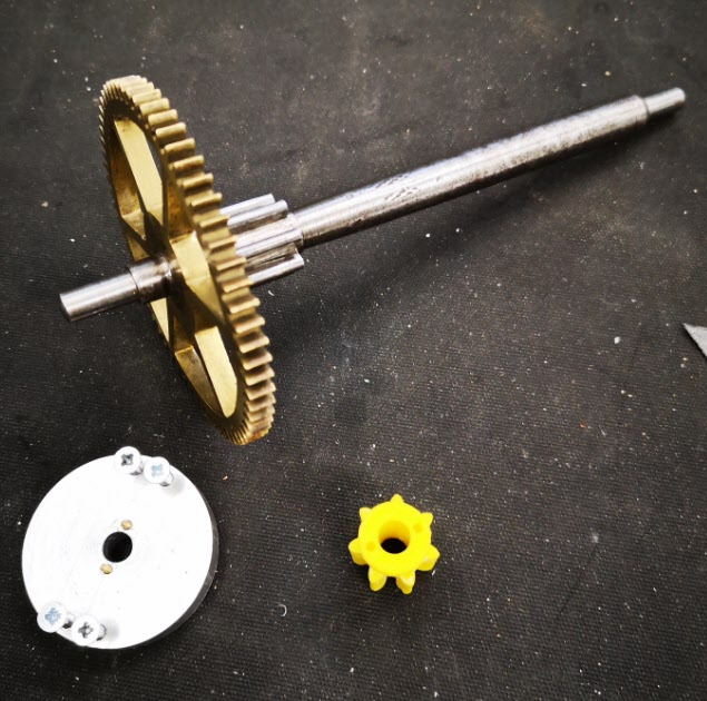
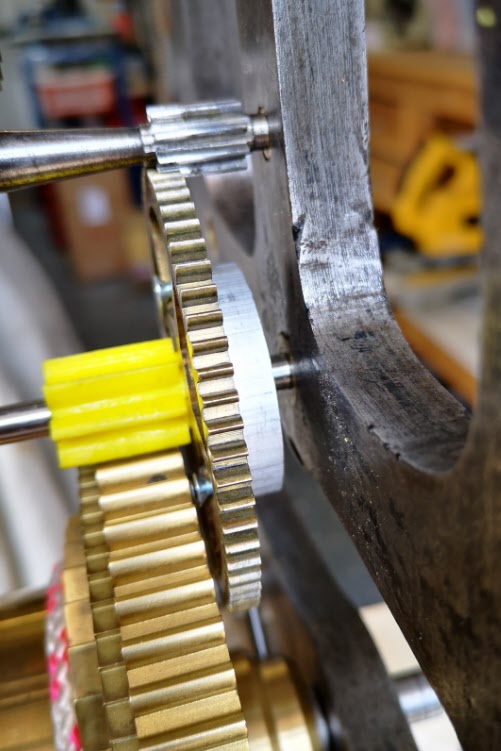
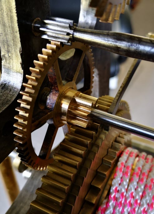
I am currently immersed in creating parts for an old turret (church) clock as pictured below.   My wife put it down as a JSN job but once again the challenge it presented won the day.  

view of the church clock as delivered to me to work on
Not a pretty sight but things do seem to move and things are certainly missing.

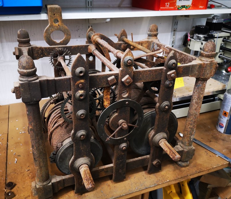
The client found me from my blog entry about creating the Brocot wheel in CNC.   His clock as you can see is missing the pallet arbor, pallets, crutch and arbor suspension bracket.  If that wasn’t enough it also needs a new escape wheel.  This is very similar to the aforementioned Brocot wheel but smaller in size.  Fortunately the old escape wheel was still in place but in poor shape with the teeth ends fairly battered and one tooth partially missing.

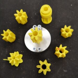
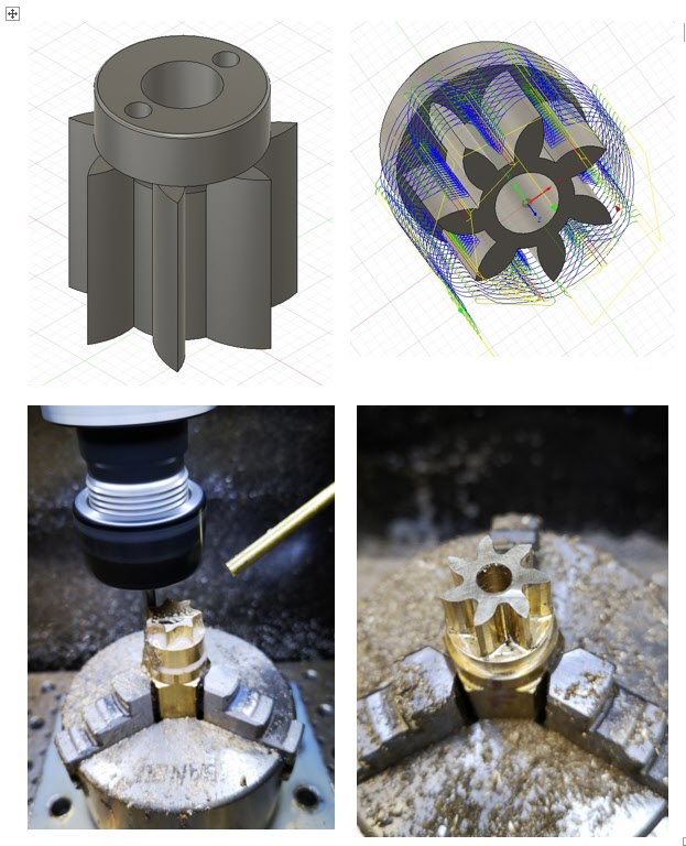
I created the CAM for the new escape wheel in Fusion 360 and then from the wheel design created the geometry for the pallets.  (There is a great document created by the BHI as part of their DLC called ‘Drawing Clock and Watch Escapements’ that helped on this as did W.J. Gazeley’s book ‘Clock and Watch Escapements’). In order to check the pallet design I decided to first of all print a 3D model.   The printed part looked like it would work when tried against the original battered escape wheel.

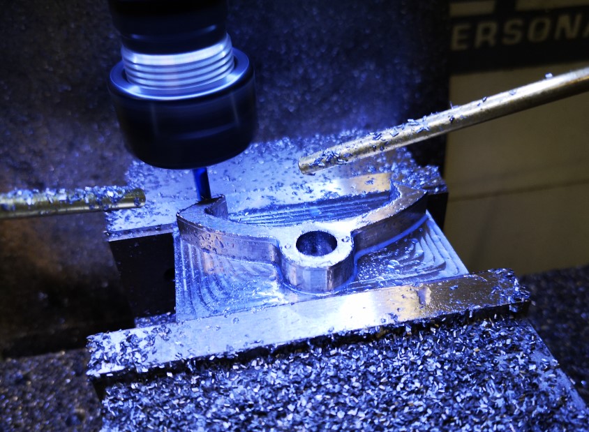
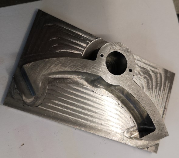
Next step in my evolutionary process was to make an aluminium version on the Tormach CNC.   I used a superglue mounting block and cut the pallet profile for the full 10mm stock depth and down to the blue mounting masking tape.   Because the aluminium was so soft and I kept the DOC gentle this turned out well.

Although the aluminium version worked very well and helped me prove the working of the clock,  aluminium is too soft for clock pallets.   A steel set would now needed and I opted for 20mm ground flat stock as the ideal material.  

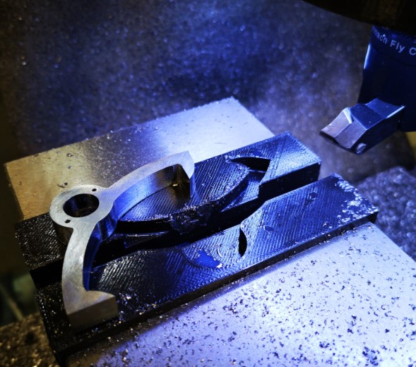
Side #1 was cut while being held in the machine vice on parallels.  A 2mm thickness of stock was left as the gripping layer.   All went to plan.

running side 1 of the clock pallets designed in fusion 360 and running on the Tormach 440 CNC mill
Side one machining of the clock pallet. An 8mm 3D Adaptive has completed and a 4mm follow on is now being run to clean up the finish.  Note the newly installed second Fogbuster nozzle.
Side one of the clock pallets completed showing the residual stock to leave as a side two operation
Finished side 1 operations and ready to invert to remove the residual stock used to grip in the vice jaws

Side #2 now became the headache.   I could have used the super glue bonding of the stock as per the aluminium version. My twitch was that this would leave very little of the pallet material remaining to act as a secure bonding face with the superglue.  Given I was cutting steel there was every chance of things parting company.  I could hold the model inverted in the vice but there was a real danger of the nib tips getting crushed.   Not a good idea.

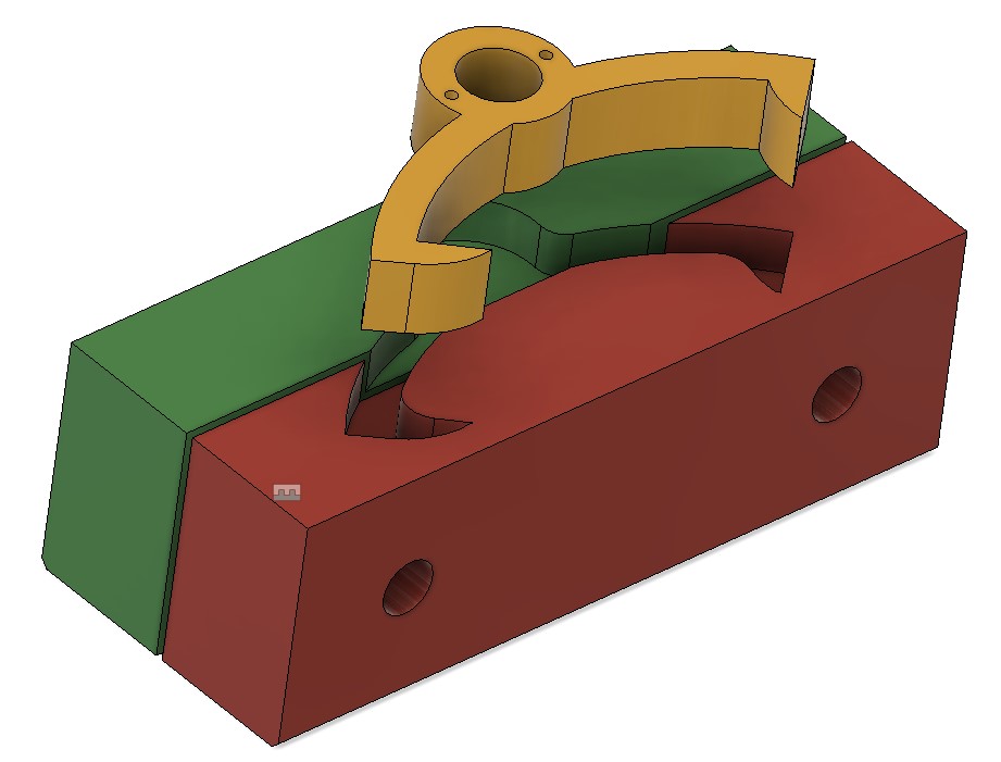
Clearly the right solution was to make a pair of soft jaws to grip the pallet shape while I was decking off the side #2 residual 2mm.

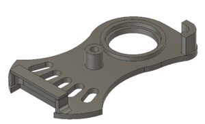
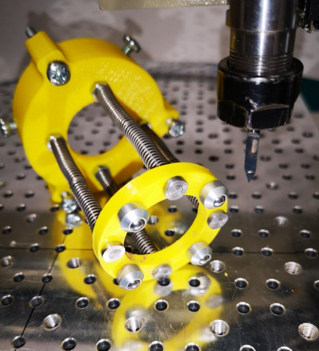
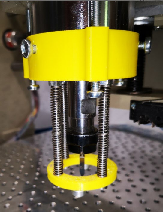
Now here is the light bulb moment.   I designed the soft jaws in Fusion so they would swap out the existing steel jaws on my machine vice.   This is a straightforward process using the Project function.   The best demo of this that I have seen is by Cough42 and is worth a watch.

pictorial view of the pallet soft jaws to allow side #2 material to be removed
The jazzed up Fusion view of the soft jaws (red and green) and the finished pallet shape that gets gripped in them.

I was about to order some aluminium stock to make the soft jaws when the 3D printer winked at me from the corner of the workshop.  Could I print the soft jaws on the printer and get enough grip to allow the last 2mm to be decked off ?  This had to be worth a try and had the advantage that I could be getting on with another of the clock components while they were printing.

Taking this route I decided I would need to modify the design in Fusion.   The 3D printer always leaves cavities a bit under size.  I used Fusion’s Offset Faces to increase the profile shape by 0.2mm all around.  I set the gap between the two jaws at 1mm.

Print time was around 2.5 hours for each each jaw.   With CAM and setup time, running them in aluminium would have been similar.   I gained the 5 hours to do something else.  (i.e. Drink tea watching the mill ….)

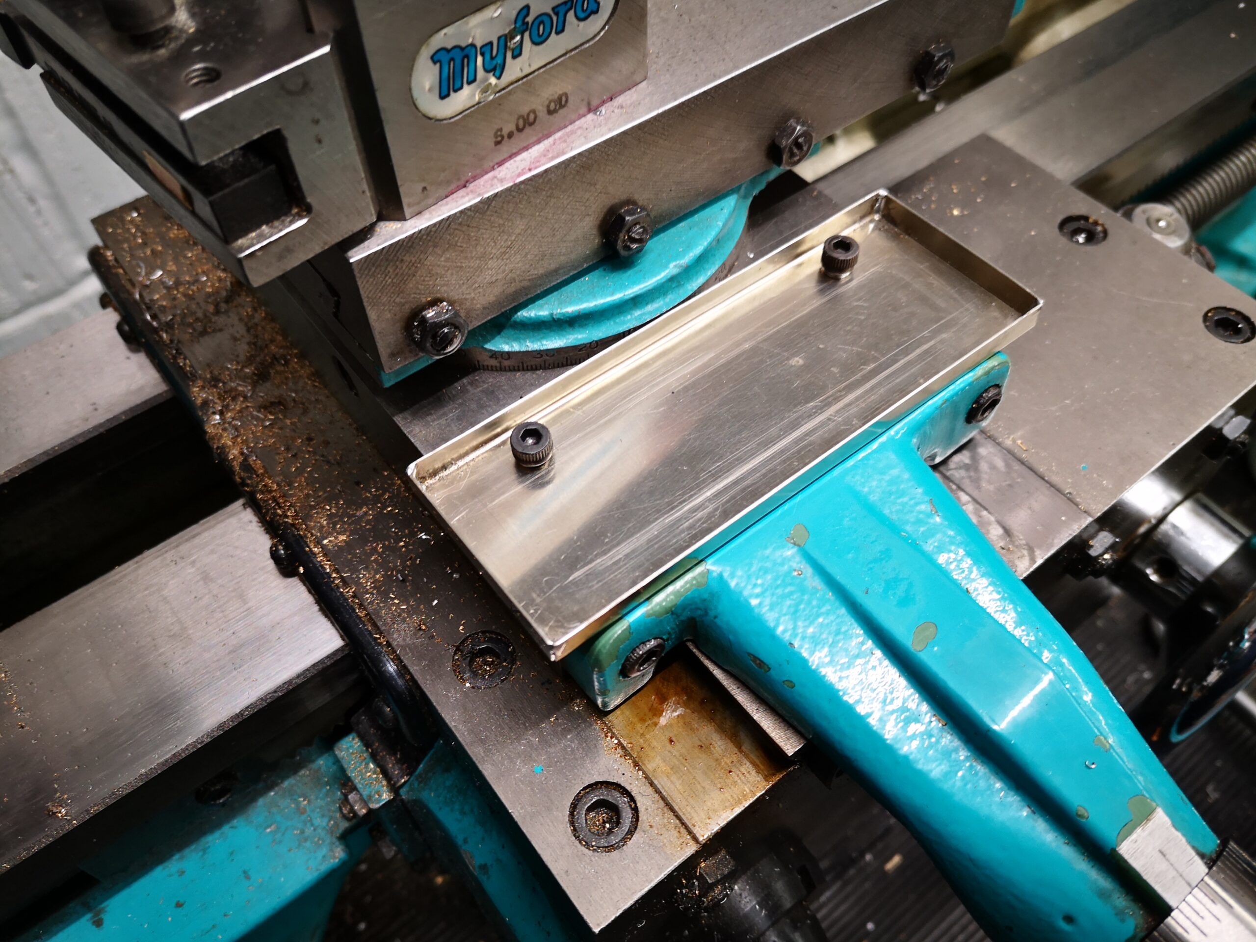
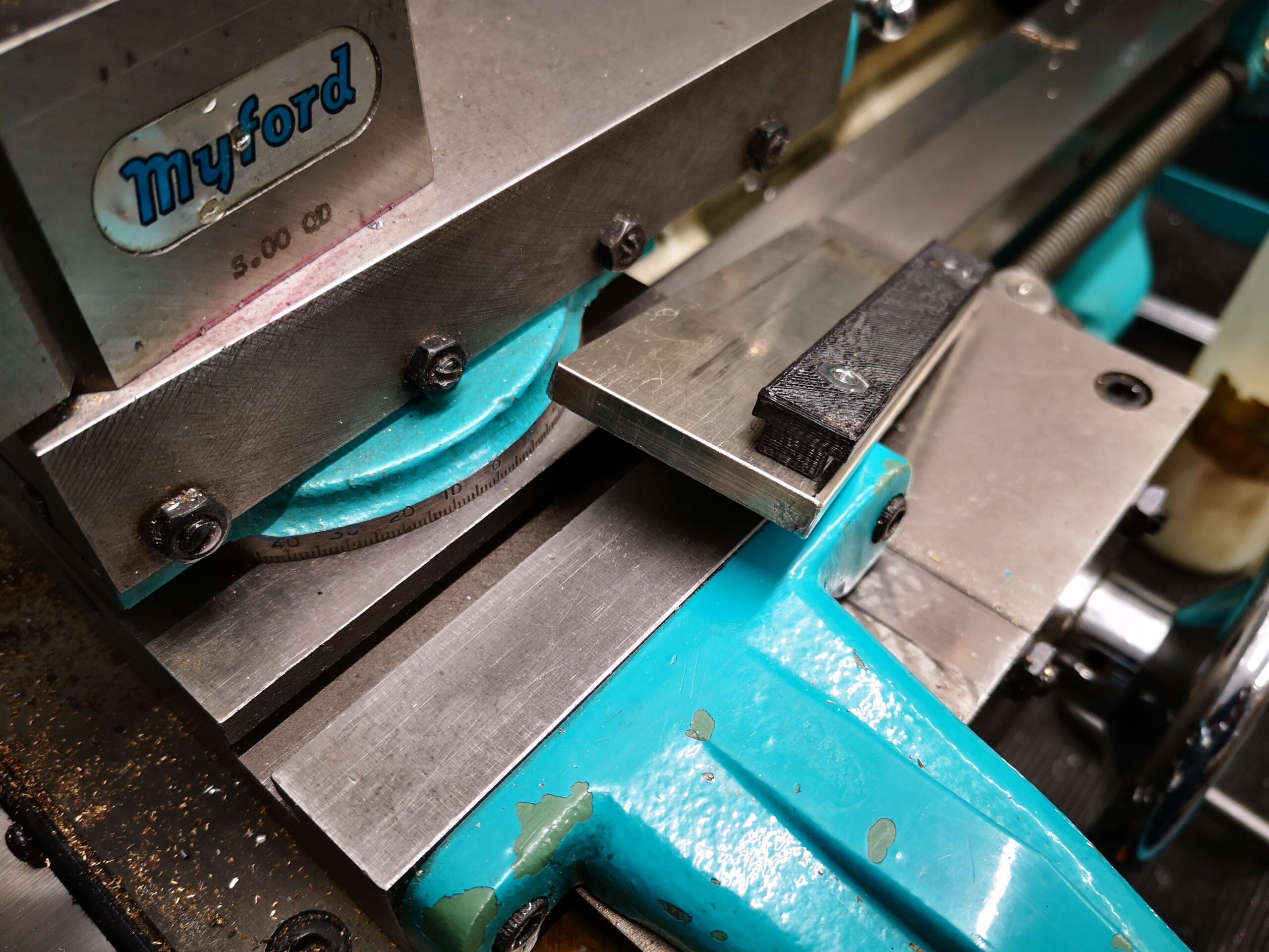
The idea worked.   The PLA tightly gripped the inverted Side #1 profile while I decked off the 2mm residual stock.  I didn’t go too aggressive on DOC.

finished pallets with PLA soft jaws
View of the finished pallets with the PLA soft jaws in the background mounted in the machine vice

 A set of PLA soft jaws – not a radical idea but food for thought.   

Aluminium soft jaws are essential if you are going to be undertaking detailed feature machining of Side #2 but if it is a simple decking skim then PLA would seem more than adequate.  Soft jaws are 1 off items dedicated to a particular part.   They are consumable as is the PLA but the PLA versions are overall quicker to produce.

This has been another situation where what would have been a no brainer ‘this is how we normally do this’ turned into a ‘how else could I do this with the resources at my disposal and make life easier ? ‘.  It is that lazy side of me shining through yet again …..   

Onwards to the next phase of the clock activity.

Similar or related subjects : –

Myford Lathe ‘Bits’ Tray

A Rainy Day Job

Browsing this months copy of ‘Model Engineering Workshop‘ I was taken by the idea published in the Readers’ Tips section by Bernard Towers for his ‘Bits and Bobs’ tray for his Myford lathe.   A simple but obvious idea.  Quite often I am machining small parts or need to make drill changes and the related items all get lost in the swarf, tools and detritus that has accumulated in the tool tray.  Either that or I put them somewhere ‘safe’ on top slide and they get knocked off and lost …. we have all been there.

It was another grey and miserable lockdown day outside so the idea looked worthy of an hour or so of rewarding therapy.  The nice part about Bernard’s design was the ability to slide the tray in and out on the top slide front edge with a spring loaded T slot retaining strip.

I had inherited a stock pile of surplus nickel silver flat pack RF screening cans with one or two pieces having pre-etched folding lines that would match the size and shape needed.  Only a fourth side needing to be cut and hand folded.  Conveniently these folding lines were just at the right height for the tray walls so they would not foul the cross slide rotation.   Once all four sides were folded up a fillet of solder was run down each corner to seal it and any sharp edges removed.   Nickel silver is one of my favourite fabrication materials being rust free, strong and easy to solder.

The tray is held in place with a length of T slot material and I created this as a 3D print in PLA.   I included hex profile holes on the lower surface to take M4 Nyloc nuts.   This meant I was inverting the retaining construction as shown by Bernard.  I also used cap head screws to mount the pressure retaining springs.

A lovely and useful time filler project and I am indebted to Bernard for publishing his idea in MEW.


Similar or related subjects : –

3D Printed ESAB Warrior Tech Helmet Hinge Latch Plate

My TIG welding frustration suffered more than usual the other day . 

I have an ESAB Warrior Tech helmet which works really well when welding but it would not stay flipped up when I wanted to see things in daylight.   Every time I leaned forward the helmet would drop down over my eyes and thump me on the chest.  Added to the fact I was trying to TIG some thin wall tubing I was no in no mood for distractions.

Before the helmet joined the happy hunting ground over the neighbours fence I took it apart to see why the latch up action was not working.   Inspection revealed that the backing plate had cracked around the latching cam.

I could have bought a completely new head band assembly but the part in question might just be 3D printable.   The Fusion 360 sketch ended up being very complicated based on eyeball guesses on curves and centres but on the second version I had a printed replacement which did the job …. for the time being anyway.

3D printed ESAB Warrior Tech latch plate replacement
The final version of the replacement plate for the ESAB Warrior Tech welding helmet latch.

If anyone is suffering from a bruised chest let me know and I will forward the Fusion file.

Similar or related subjects : –

Workshop resources all coming together like clockwork

Another JSN Job ?

You know how I keep on going on about how solutions to problems are often solved by coming at them from different and often unconventional directions, by utilising and marrying available resources ? It was a philosophy that I encouraged in my team while running my business and it has carried over into my way of working in retirement.   A recent job brought his home to me.

A client had a very old clock that had had a new barrel wheel made and fitted but the clock would not run for more than a few minutes.   There appeared to be an incompatibility either between the modulus of the new wheel and its mating pinion or the shape of the original pinion did not match the shape of the new wheel. 

If you spun the barrel wheel you could feel the resistance build up as the synchronisation between the two profiles drifted out.   Adding extra weight to the barrel helped but did not solve the problem.

So what to do ?   

The barrel wheel was serious engineering and I did not fancy making a new one.   The existing mating pinion was a seven leaf format and its leaves were what you might call pear drop shaped rather than the expected profile.  The pinion arbor had a 72 tooth wheel driving the next part of the clock train but we did have a spare one of these to hand from the minute dial.

Calculations from the geometry of the barrel wheel resulted in a modulus        figure of 1.86.  A rather large value and not one that conventional cutters are readily available for.  The pinion was perhaps something that could be drawn in Fusion 360 and then made on my Tormach CNC PCNC440 milling machine.   The only snag was that the profile needed on the pinion would likely be weird and the world’s supply of brass could diminish rapidly while getting the profile correct.

Using Gearwheel Designer I created what would be the expected profile for a 7 leaf pinion with a modulus of 1.86.  This was exported as a DXF line drawing into Fusion 360.  This outline was extruded in Fusion into a 3D design and a boss was added to mount the 72 tooth wheel. 

The design was 3D printed on my Sindoh 3DWOX printer and was mounted on a 6mm silver steel arbor.   I added a driving disc that interlocked with the printed pinion and the crossings on the wheel to drive the assembly.  Surprise surprise it didn’t run but it did mirror the regular pattern of stiffness of the original pinion. 

Original arbor , pinion and wheel with the driving disc and a test profile
The original arbor, pinion and wheel together with the driving disc and a 3D printed pinion test profile. The driving disc has screws to lock it to the wheel and two protruding pins to lock into the 3D printed pinion profile under test. The 3D printed profile was a tight pressure fit onto the new 6mm arbor.

I now had the test bed for quickly making and testing different pinion profiles. There followed a number of hours watching the engagement progression of the profile of the pinion into the barrel wheel and then trying to conceive a profile for the pinion that might run. 

3D printed test profiles
Various trial profiles and the temporary driving disc to engage with the 72 tooth wheel


Test pinion in place on the new arbor
A test pinion in place showing the 72 tooth wheel and the driving disc

Fusion 360 made this process so easy and round 10 printed test profiles later I had success with a clock that now ran.    The driving weight on the barrel was around 11kg and it looked to be worthwhile wasting some brass making a ‘proper’ one. 

I took the 3D design and produced CAM code in Fusion.   This would cut the profile ‘on end’ using an adaptive first cut with a 4mm end mill followed by rest machining the remaining material with a 2mm end mill. 

Images of the Fusion 360 process of creating the new 7 leaf pinion
The Fusion 3D model of the pinion, the CAM simulation of the leaf cutting, first adaptive cut of the leaves and rest machining final pinion

The resulting brass pinion was mounted on the arbor and the clock ran with a strong beat.   As expected the brass pinion gave less surface to surface resistance than the 3D printed part and the barrel driving weight was now able to be reduced down to 6.25kg.

new pinion mounted in the clock
The finished pinion mounted in the clock on the new arbor

I ran my Microset Timer on the clock overnight and had a first off timing error of 5 minutes per day which was fixable with a pendulum tweak. The movement had an instability of a few seconds per day which was quite astonishing.

The conclusion of the experience is that at first glance this seemed like a conventional pinion cutting exercise …. but M1.86 cutters are not readily available.   If a cutter could have been found at less than a King’s Ransom it is likely that the resulting conventional profile would have been wrong to match the barrel wheel.   

The alternative route that was taken of Gearwheel Designer to Fusion to 3D print to Fusion CAM to CNC machining solved the problem albeit with a final weird profile.    The purists and traditionalists will groan.   There will be a gnashing of teeth and a pulling out of hair. 

Does it really matter if the result is new life for what could have become a heap of scrap metal ?

Similar or related subjects : –

Floating pressure foot for the CNCEST3040T mini milling machine

A new idea for keeping PCB material flat while milling artworks

The vacuum plate mentioned elsewhere on my blog serves me well when milling printed circuit boards on the Tormach PCNC440.   It keeps the PCB material flat and makes the cut widths repeatable when using V cutters.

The plate cannot be easily used on my CNCEST3040 due to the restricted Z height.   We have experimented with various techniques to keep the PCB material clamped flat on the smaller mill with varying degrees of success.

Idle hands and brain during social distancing has produced a possible solution that might be of interest and stimulation to others.   It consists of a circular pressure ring that sits around the spindle chuck and tool.   There is a second ring that sits on the spindle body connected to the lower ring with rods which have coaxial springs pushing down on the lower ring.   The magic is to use mini ball transfer units on the lower ring to press down on the PCB and glide friction free around the PCB as the cutter does its stuff.  The assembly is held in place on the spindle with 3 gripping screws.   The downward pressure is adjusted by 3 screws that press against the spindle mounting frame.

The ball transfer units come in all sizes and are very common in baggage handling systems at airports and in industrial conveyor systems.  The ones I used came from RS and have a 4.8mm ball and a M2 mounting shank

The prototype was made using 3D printed rings.   There is an image below.  Apologies for the yellow PLA but finding any PLA at a decent price is very difficult in the present circumstances.

Bottom view of pressure foot for CNCEST3040
A view of the underside of the lower ring and the four ball transfer units. In the background is the upper ring that sits around the spindle with the pressure adjusting screws and the spindle gripping screws.
Pressure foot for the CNCEST3040 in place on the spindle
View of the pressure foot in place on the spindle showing the tension adjusting screws and spindle grip screws

The idea seems to work and has produced some good consistent quality PCB prints.   It does have disadvantages in that you need to have a larger PCB blank to allow for the larger footprint of the pressure ring.   It is probably only of practical use for PCB milling but then the problem of flatness is less critical in drilling the board and routing the profile.

Similar or related subjects : –

Verified by ExactMetrics