Floating pressure foot for the CNCEST3040T mini milling machine

A new idea for keeping PCB material flat while milling artworks

The vacuum plate mentioned elsewhere on my blog serves me well when milling printed circuit boards on the Tormach PCNC440.   It keeps the PCB material flat and makes the cut widths repeatable when using V cutters.

The plate cannot be easily used on my CNCEST3040 due to the restricted Z height.   We have experimented with various techniques to keep the PCB material clamped flat on the smaller mill with varying degrees of success.

Idle hands and brain during social distancing has produced a possible solution that might be of interest and stimulation to others.   It consists of a circular pressure ring that sits around the spindle chuck and tool.   There is a second ring that sits on the spindle body connected to the lower ring with rods which have coaxial springs pushing down on the lower ring.   The magic is to use mini ball transfer units on the lower ring to press down on the PCB and glide friction free around the PCB as the cutter does its stuff.  The assembly is held in place on the spindle with 3 gripping screws.   The downward pressure is adjusted by 3 screws that press against the spindle mounting frame.

The ball transfer units come in all sizes and are very common in baggage handling systems at airports and in industrial conveyor systems.  The ones I used came from RS and have a 4.8mm ball and a M2 mounting shank

The prototype was made using 3D printed rings.   There is an image below.  Apologies for the yellow PLA but finding any PLA at a decent price is very difficult in the present circumstances.

Bottom view of pressure foot for CNCEST3040
A view of the underside of the lower ring and the four ball transfer units. In the background is the upper ring that sits around the spindle with the pressure adjusting screws and the spindle gripping screws.
Pressure foot for the CNCEST3040 in place on the spindle
View of the pressure foot in place on the spindle showing the tension adjusting screws and spindle grip screws

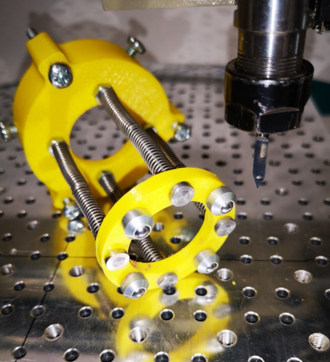
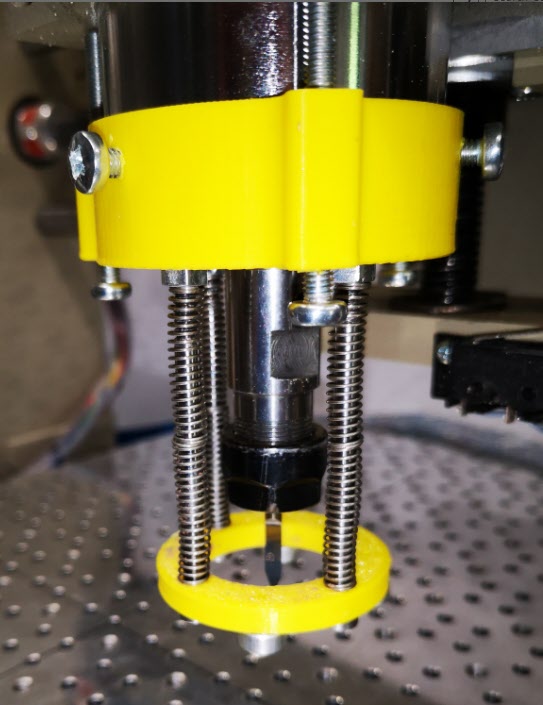
The idea seems to work and has produced some good consistent quality PCB prints.   It does have disadvantages in that you need to have a larger PCB blank to allow for the larger footprint of the pressure ring.   It is probably only of practical use for PCB milling but then the problem of flatness is less critical in drilling the board and routing the profile.

Similar or related subjects : –

Probes and Haimer Taster Modification

I have been using a Wildhorse Innovation CNC set up probe for some time now.  It works OK but sometimes the results are not consistent.   After one frustration session I decided to upgrade it to the Hallmark ITTP probe from Threadexpress in New Zealand.  

It arrived today after nearly a month in transit due to the current lock down restrictions.  On opening the package I was impressed with the quality of the engineering.  It is a nice device.  It uses the usual 3 pronged contact mechanism.   Supplied with the probe is a tube of grease that helps protect the contact reliability.  The interface cable has a 5 pin DIN that plugs into the Tormach expansion socket and the shank is a standard TTS compatible size.

hallmark ittp cnc probe mounted on the tormach pcnc440
The Hallmark ITTP probe mounted in the Tormach ready for setup and testing.  You can also see my angel ring light illuminator and Hall Effect tool height setter.

I ran through the initial preparatory procedure and then loaded it into the Tormach 440 spindle.   Pathpilot has a number of excellent set up routines to adjust the probe and make measurements.  One of these, the Effective Tip Diameter is quite critical.  All this went to plan and very quickly.  Some initial probing gave repeatable and accurate results so first impressions are good.  

Some of the Tormach PathPilot CNC probing routines
PathPilot probe setup screen and the two probing routine screens.

I’ll give some updates as the probe gets pressed into service but my first impressions are good with repeatable accurate readings.  

In the course of checking out the ITTP probe I needed a reference cross check on the various setup measurements.   My Haimer Taster seemed a bit erratic and on inspection I discovered the axial shank holding bolt had worked lose.  This meant a re-calibration of the eccentricity of the probe point would be needed.  

The alignment process involves adjustment of four grub screws in the shank body.  These tweak the ’tilt’ of the shank to get a concentric rotation of the probe ball point.   As there are four screws I use two hex Allen keys to make the adjustments to each in line pair.  This is quicker than with a single hex key being swapped from side to side.  It is a bit like the process I use when centring a 4 jaw chuck. The adjustment is done against a dial gauge riding against the probe ball point.   Once you get the knack this process doesn’t usually take too long using the two key method.   

The frustration is that the Allen keys provided with the Haimer are a bit chocolate based and the ends chew up easily.  The result is you tighten a grub screw and the hex key end twists and gets jammed into the hex socket in the grub screw.   While trying to waggle the jammed key you mess up your carefully made adjustment.  Aaaargh !

I ground back the worn end of the Allen keys to clean up the hex profile but they quickly degraded.   In the end I took the grub screws out completely and replaced them with some M4 cap head bolts.   Joyful !

adjusting screw change on Haimer Taster concentricity adjustment
How ugly is this ? Replacement screws on my Haimer Taster

Yes I know it doesn’t look pretty but it is now a real pleasure to make the adjustments with a couple of larger T wrenches.  It is probably a criminal thing to do to such a lovely instrument but life is too short.

Next job will be to modify the arrangement of my tool sharing junction box on the Tormach expansion port so my Hall Effect tool height setter and the ITTP can share the input.

Similar or related subjects : –

Tormach MicroArc and Fusion 360 and 4th Axis

Tormach MicroArc 4th Axis Arrives

At last a 4th axis drive for the Tormach PCNC440 ! 

tormach microarc 4th axis

I have waited 4 years for this to be available and did not hesitate to put in my order to Tormach for one of the new MicroArc drives.  Probably the best way to get a good idea of this product is to watch John Saunders’ video.

The MicroArc wasn’t a low cost buy and because 4th axis was not around when my 440 was originally shipped, I needed a fitting upgrade kit as part of the order.   Having placed my order with Tormach it took exactly 7 days for DHL to arrive on my doorstep with the shipment.  Quite amazing considering the difficult times we are experiencing at the moment.

It took me about one hour to fit the new stepper driver and additional wiring.  As ever there were good clear instructions from Tormach.   I switched on the 440, enabled the 4th axis in PathPilot and I could control the A axis from the PathPilot screen.   Very impressed.

I watched John Saunders video on the MicroArc and how to do 4th axis programming in Fusion 360.  I drew up a simple model in Fusion but could not get it to produce working GCode.  I had some comms with John and he gave me some pointers.   The model had a rotational repeat pattern but while I could run a single op code, if I tried to run the rotational pattern the post processor came up with an error message and would not output any code.

I thought at first it was because I was only using a Fusion hobbyist licence and that 4th axis maybe was not possible.   A really helpful dialogue with Shannon McGarry at Fusion cleared up that issue so it must be something else.

After some experimenting I discovered that you have to set the axis of rotation in the post processor dialogue options list.   All then worked fine. 

We are up and running on 4th axis !

Similar or related subjects : –

Making a Brocot Escape Wheel using Fusion 360 and Tormach PCNC440 CNC milling machine

A Steep Learning Curve

My wife has presented me with a sign that has just got JSN written on it.  It is to remind me when I answer the phone to a ‘can you just do’ enquiry…… to Just Say No.

I try my best to live up to her expectations but sometimes something comes along that should really be a JSN job but which scratches an itch.   You know what I mean.   You think about it and you do all the right mental arithmetic in your head and the answer keeps coming back to the same – don’t even think about it.  But the the other side of my brain is screaming at me … what a challenge, what a learning experience, what fun to have a go at it.   Providing the asking party is aware of your thought process or lack of it and accepts that it might just go belly up and never come to fruition then why not ?

Back to the story – 10 days or so ago I had a call from David Pawley who is a turret clock expert extraordinaire to say someone he knew was after an escape wheel for a turret clock and was desperate.   David passed on the details and a couple of days later the potential customer arrived on our driveway.  After a suitably socially distant conversation and a rubber gloves inspection of the old damaged wheel …. I got sucked in and turned the JSN sign over to face the wall.

Brocot 30 tooth escape wheel
The original Brocot 30 tooth escape wheel that needed a new one making

As you can see it is not an ordinary escape wheel and I had to delve into one of my favourite books ‘Wheel and Pinion Cutting in Horology’ by J Malcolm Wild FBHI in order to learn about Brocot Escape wheels.   Malcolm is a great guy and his book should be on any clock experimenters bookcase.

The Brocot is no ordinary escape wheel.   In fact it is a real challenge.   Not a simple fly cutter job.  Traditionally it would be cut in an indexing device such as a lathe with two different cutters, one for the curve and one for the notch.  I didn’t have these so I thought I would probably upset the traditionalists and try to use CNC.

Read all about the adventure and see the result in this pdf download …….

Similar or related subjects : –

Experiences and understanding FlatCAM PCB milling program

FlatCAM Write Up – Experiences and Procedures

After a lot of editing I think the attached document will give an in depth understanding of how to use FlatCAM based on Version 8.5.   The document is based on our experiences and a steep learning curve.  We now have a repeatable process for milling PCBs from Gerber and Excellon files exported from a PCB design package.

The document may well have mistakes and we would appreciate feedback good or bad.

Latest version is now based on FlatCAM v8.991

FlatCAM v8.991 and milling pcbs 2021

Similar or related subjects : –

Verified by ExactMetrics