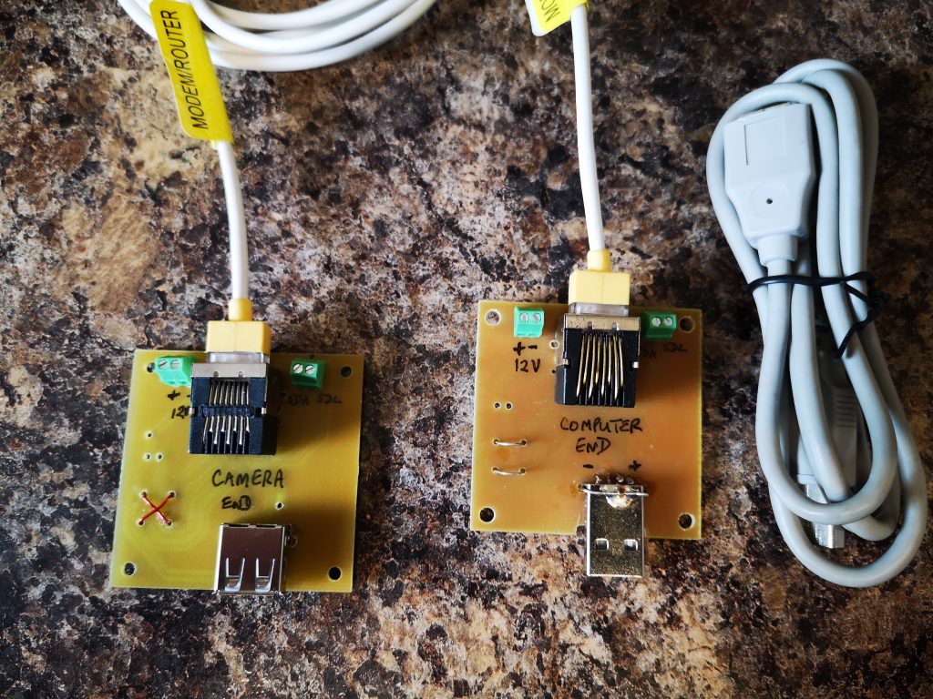
One of our group of ‘silver experimenters’ is building an Arduino based celestial camera tracker. This will be deployed in the garden and he needed all control to be routed back inside the house. The garden installation consists of a USB webcam mounted on a servo controlled platform all powered by 12V DC.
We pondered long on how we might remotely connect to the garden. The crucial thought was that the Arduino servo board was a two wire interface using the I2C format data exchange. Given that the USB needed four wires and the DC supply two wires we had a need for an eight core cable connection. It seemed like a length of CAT5 cable would do the job and we could elegantly use standard CAT5 sockets.
The PCB was designed in Design Spark and milled on the Tormach PCNC440 using FlatCAM.
There is a problem with running USB over more than 5m but I did some tests at 10m and all seemed fine which should be adequate for the application.
The breakout boards had a male and female USB connector fitted and the connections had to ‘cross over’ on one of the breakout boards to maintain continuity. We also paired the Data + and Data – connections with the +5 and Ground twisted pairs in the CAT5 so the Data + and Data – were not twinned together.
Nothing technically magic but a simple solution to a project need.
I & J Arc Code Calculator (with updated spreadsheet)
I had a need to hard code a circular PCB cut out CNC code that would cut four arcs around a milled PCB and leave four breakout tabs to retain the board in place in the blank until the job was finished.
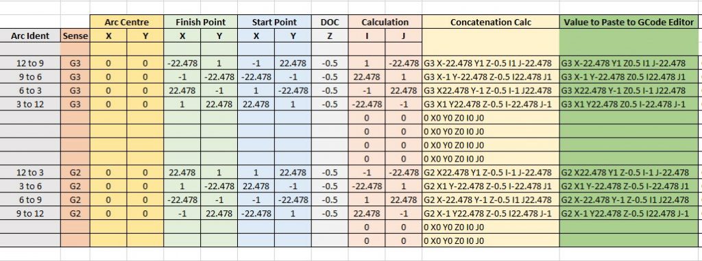
To create I & J codes you need to know the start point, end point and radius of the arc. The end point becomes the X and Y. The delta X and Y location relative to the radius centre point X and Y becomes the I and J values. You can also add a depth of cut value for Z as part of the block. Note that the Arc is assumed to run anticlockwise when using a G3 code running from start point to finish point. Use G2 if you want a clockwise motion. The principle is the same with both rotations.
You end up with a block code of the format G3 (G2) Xa Yb Zc Id Je where a,b,c,d,e are the coordinate values. I found that working with positive and negative values when trying to find the I and J values relative to the centre was hurting my brain. A spreadsheet was needed …..
Screen shot of I and J calculator spreadsheet for G2 and G3 coding with examples based on CW and ACW arcs around quarters of a circle with small gaps between each arc.
You can download the sheet as a ZIP file from the link below.
I had been using Hall Effect devices to modify my William Smith Gearless Gravity Arm clock and had been surprised by their ease of use and repeatable trip points. (More about this to follow in a separate post).
I had also been frustrated with my inability to set tool heights reliably in PathPilot despite using various methods all of which didn’t want to agree with each other.
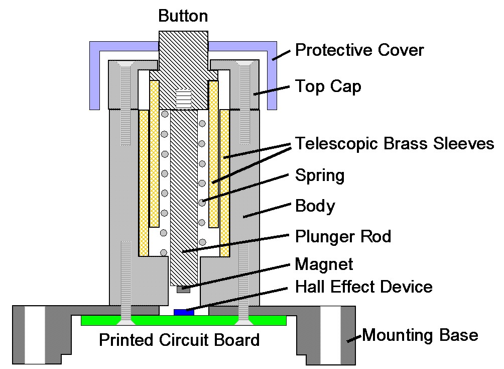
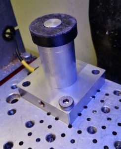
This resulted in the construction of a Hall Effect based Tool Height Setter that appears to solve the problem. The write up is lengthy so I have committed it to PDF for download but here are a couple of images to give you an idea of the result.
A simple cross section sketch of the tool height setter concept using a Hall Effect sensor
Finished tool height sensor mounted on the PCNC440 milling table
Previously on Woody’s Workshop … I had spent time trying to get a consistently level PCB blank clamped to the tooling table ready to mill the traces using CNC. The results were not too bad but being anally fussy it left a bit to be desired, particularly if the board had a large area which magnified the variations.
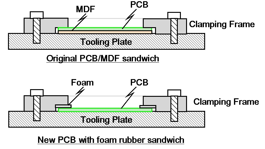
Any variation of the level of the PCB top surface will produce variable width cuts when using a V shaped cutter. I had machined a clamping plate which was a simple open frame with a clamping step equal to the PCB thickness (1.6mm) and a sheet of MDF or hardboard as a sacrificial backing board.
Despite having more clamping screw holes than a magazine burst from an AK47 I still ended with the corners of the PCB being a few thou lower. Results were shall we say ‘variable’. I had reason to run a new prototype board this week and once again hit the same frustration. In the end it was a sit and look at it and have a think session.
The resulting revelation was maybe the sharp edges on the step are applying too much pressure ? What if I were to be more gentle with the clamping ?
I cut some strips of thin foam rubber and put this into the step such as to push down on the PCB. As a quick test I only fastened the frame down using the four corner holes.
Sketches showing the two methods of clamping the printed circuit board ready for CNC milling
Absolute magic. The PCB surface hardly moved the Hamer needle at any point on the surface. Milling result was an artwork to be proud of.
Issues – the current step on the clamping frame is meant to clamp to a hard stop based on the sum of the PCB thickness and the sacrificial material thickness. Adding the foam meant I had to do away with the sacrificial board. The frame step therefore needs to be deeper. The sacrificial material is essential to allow drilling to take place without breaking the drill as it runs into and potentially damages the tooling table. (For the board in question I drilled to only 1mm and then over drilled by hand off line to the mill).
So a worthwhile bit of experimenting and hopefully a better result going forward
Back from after a few weeks in France and back in the workshop.
Every now and then there is a project that is on the go and you can’t sit down and focus on it. It is a sort of mechanical procrastination. A reluctance to put the first pencil mark on the paper. You then suddenly find all sorts of other things that you kid yourself are more important / higher priority and you get distracted. You know that job will still be there but maybe tomorrow, not today. You suddenly develop a clear conscience about doing something else while you do some background thinking ….
This particular day started off by cleaning down the accumulated swarf (chips) in the 440 tray. Really important job. This led to a check behind the various 440 slideway bellows to see that all was well with the oiling mechanism on the slideways and the ballscrews. X and Y were fine but Z was dry. Not good news.
The 440 is supplied with a manual oiler as standard. This is a reservoir of oil and a pump/plunger which you pull out and release to initiate a slow pressure to the oil distribution pipes.
View of the manual oiler mounted on the Tormach 440
I checked the plunger and it didn’t feel like it was applying much pressure. This is not the first time I have experienced this problem. If I pumped a few times it felt better so something should have been happening at the oiling points on the Z. I disconnected each of these where I could and sure enough if I pumped hard enough some oil dribbled out but not with much pressure. Something probably not right with the plunger ?
Squeezing round the back of the mill I removed the top of the reservoir (4 retaining screws), disconnected the oil pipe union and lifted the plunger clear. The reservoir can be left in place sitting on the mounting bracket.
There is a large end cap at the union end of the plunger cylinder which I removed and sure enough I could see a mangled O ring. To get the plunger out you have to be a bit brutal. You pull the T handle plunger back out of its housing against its spring using the handle as shown above and then grip the shaft with pliers so you can then twist the handle off. What you don’t do then is suddenly release the pliers grip or the plunger will go into low Earth orbit under the pressure of its spring …
Having disassembled the plunger it was obvious that the O ring had failed quite badly. Tormach support do not offer spares as the oiler is a third party item. They do not know what size the O ring should be. Checking in my box of miscellaneous O rings it looked like a 9mm ID, 3mm thickness part would do the trick. Smearing the O ring with DC4 silicon grease allowed easy re-assembly into the piston bore and then back onto the 440. I now had lots of pressure and oil was apparent trickling down the Z slideways and ball screws. Job done. No pumping needed, just one pull out of the piston handle was generating a slow release of oil to the key areas.
The job I should have been doing was still sat on the bench glaring at me but psychologically I was doing something more important.
Next problem was the Fogbuster air activation valve. Under CNC control this reliably switched on but sometimes would not switch off when commanded to. There are various forum discussions on this problem and many contributors just replace the solenoid valve with a different version. Forum chat also recommended that electrical transient snubbers are fitted across various inductive loads in the Tormach control unit. I had some of these in my stock box (Tormach offer a kit for this). They are simply a series resistor and capacitor in an epoxy block. They are fitted across any inductive device to suppress switching transients. I dived into the control box and fitted one across the controller relay coil that switches the Fogbuster ON and OFF and another one across the outlet from the control box feeding the Fogbuster solenoid coil. See picture below.
Snubber across Fogbuster activation relay coil. There is a second snubber fitted to the lower LHS contact which activates the air solenoid. The other end of this snubber goes to the any ‘100’ connection which is mains neutral.
The problem seemed to be improved but still occasionally the solenoid did not switch OFF.
The Fogbuster solenoid has a clear housing over the activation coil connections and there is a LED inside this that comes on when the Fogbuster is switched on.
Fogbuster solenoid assembly showing the connection clear housing which plugs into the solenoid coil which in turn sits over the activating plunger assembly. There is a screw in the LHS to release the electrical connection and the nut on the top releases the coil to reveal the plunger housing.
This connection housing plugs into the coil and the mechanics of the solenoid body and is released with a screw in the end. Toggling the coolant ON and OFF via the PathPilot user interface I could see the LED responding correctly to the ON and OFF commands but occasionally the solenoid was not closing. It was therefore not an electrical problem but mechanical.
On top of the solenoid housing is a single large nut which when released allows the solenoid coil to be lifted off. This leaves two countersink screws which hold the mechanical plunger housing in place and if these are removed the plunger can be gently removed. Inside the valve is very simple. A central hole allows the air to pass through and when the solenoid is de-energised a spring forces the solenoid plunger to seal this hole. I gave everything a thorough blast with compressed air and re-assembled it. Care is needed re-assembling as there is a tiny O ring seal on the plunger cover. The solenoid now responds correctly to the PathPilot commands.
Another tick. Job done. Warm glow.
That other job is still sat on the bench glaring at me ….