Milling vice stop for non grooved vice jaws

Another Job Ticked Off

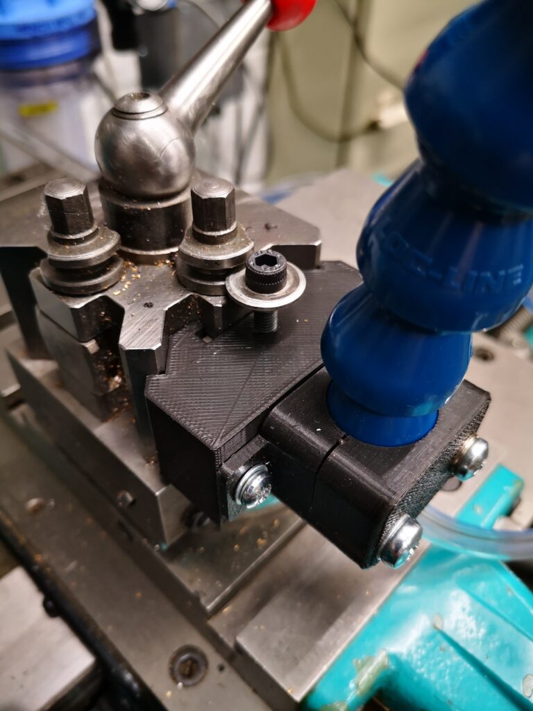
There are a number of lower cost CNC milling vices (vises) available on the market that do not have jaw geometry with grooves for tooling fixtures and vice stops.   Admittedly their jaws could be machined to add this facility but many of these vices have hardened jaws which presents more of a problem.

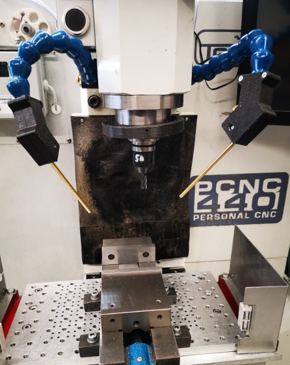
My CNC vice came from the UK supplier ARCeurotrade and is from their ARC Versatile SG Iron Milling Vices range.   I have the 100mm wide jaw version and the jaws are  just over 11mm (7/16″) thick.

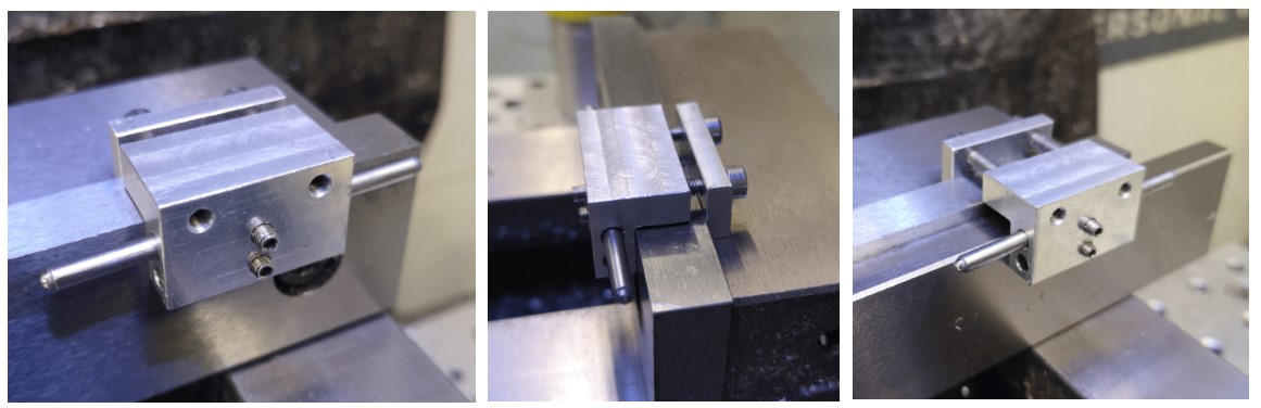
I have a simple plate that acts as a stop  that is flush with the end of the jaws.  This makes use of existing holes in the vice body but often I need to have a stop internal to the jaw footprint.  Juggling then results with all manner of Heath Robinson solutions.

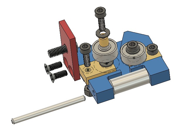
My design is simple and clamps onto the thickness of the jaws.   

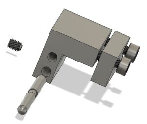
There are two M3 clamping screws and there is enough adjustment on these to allow a parallel to also be gripped should it be needed.

CNC vice stop showing clamping onto the vice jaw and also when used with a parallel

I allowed for two positions for the stop rod and the rod is held with a grub screw in each.   There is a central burr clearance neck on the rod so the grub screw does not damage the surface of the rod and make removal difficult.  Clearly the rod could be simplified to have just a single fixed position.

The rod can have rounded ends or it can have ball bearings glued into a cavity on each end of the rod.   The ball bearings would give a higher resilience to damage.

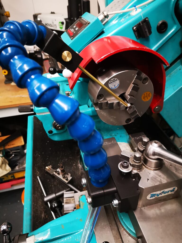
So nothing really complicated or rocket science with just an hour or so of workshop pleasure.   The size can be adjusted to suit your vice jaws and the material can be whatever is in the junk box.

Here is a link to the 2D drawings that were created in Fusion 360.

CNC vice stop Drawing v3

Similar or related subjects : –

Burgess BK3 replacement lower blade guide

Burgess BK3 Final Modification – Lower Blade Guide

This is the final piece in my Burgess BK3 bandsaw upgrade jigsaw.   Having successfully replaced the top guide with a double bearing assembly my attention turned to the lower guide.  Using the same principle as the upper guide I came up with the following assembly.

Burgess BK3 bandsaw replacement lower guide assembly
Stylised Fusion 360 image of the replacement lower guide assembly on my Burgess BK3 bandsaw

This seems to work well and is straightforward to implement.   The bearings are standard 1/2″ size parts from Bearing Boys.   These need a small brass bush to mount them on the sliding brass blocks.  The blocks need a single M3 washer to space the bearing from the block and the body.

The blade pressure roller is made from silver steel and can be heat treated to improve wear from the blade edge.

The mounting bracket arm picks up on the original M5 mounting screw concept.  The bracket could be milled onto the main body as a CNC operation but the two part assembly works fine and is very rigid in operation.

Here is a set of drawings for my BK3 lower guide assembly

The link below is a complete set of notes and drawings pulled into one ZIP file to cover all the modifications I have done and separately document in my blog and other author’s notes that I have come across.  I hope that helps.

Updated file link to BK3 Modifications v2

Similar or related subjects : –

Repairs to an ancient Thwaites clock completed

I have mentioned my activity on the Thwaites clock in a couple of blog posts and I can now confirm the work is complete.

Thwaites clock as originally received prior to the work taking place
The Thwaites clock as received before work commenced

This has been an interesting challenge and I am pleased with how it has worked out.  Once again I am impressed by the way that modern techniques and technology can all play their part in achieving a result that once upon a time would have been impossible using traditional circumscribed knowledge.

There is a full write up here on the Thwaites Clock Activity for anyone interested.

Similar or related subjects : –

Fogbuster update on my Myford Super 7 lathe

Plan B Fogbuster Mounting on the Myford lathe

Of late there has been a long thread running about Fogbuster use on the MEW forum.   This set me thinking.  The forum debate centred on whether mist lubricant or flood coolant was more or less healthy.   For hobbyists the consensus seemed to favour the mist coolant.  This was with the proviso that the jet and coolant mix is carefully balanced.  An interesting point was made about ensuring the air stream was pointing away from the operator to avoid blowback.  If all is good you should not be able to smell the lubricant.   (N.B. I use QualiChem Xtreme Cut 250C at around 8% dilution).

The installation on my Tormach PCNC440 is fine with respect to blowback at the operator.  Both nozzles are on flexible mountings and can be easily directed towards the back of the mill.  (See prior post).

My installation just completed on my Myford Super 7 is not quite so perfect.   I was using a T slot at the back of the saddle as the nozzle mounting.  This meant the nozzle was playing on the back of the workpiece and towards the operator.  Perhaps with hindsight not the most healthy option.   OK so I don’t use lubricant on the lathe that much as most of my work is brass and aluminium so maybe less of a critical issue.   Because of the infrequent use I wanted the Fogbuster to be quickly demountable until the next steel job comes along, hence the T slot idea.

I have a Myford Quick Change Toolpost fitted on the Super 7 which has two tool holder positions at right angles to each other.  It struck me that the Fogbuster could be mounted in the QCTP unused slot.   This would allow the air jet and lubricant to point forwards towards the workpiece.  Normally I would have the empty slot on the far side face so a boring bar can be dropped into place.   By rotating the QCTP through 180 degrees the spare slot would sit nearest the operator and be ideal for the Fogbuster.  

I didn’t really want to dedicate a steel tool holder to the Fogbuster so I created a 3D printed version.   This picked up on the prior mounting holes I had modelled in the flexible clamp.

I needed to make sure my 3D printed profile was a good fit in the QCTP so after fully modelling it I moved the time line in Fusion back to the profile extrude and reduced this from 26mm to 5mm and ran a test print on just a 5mm depth version.   This allowed a quick print to be done which gave me feedback to do some minor edits.   The timeline then was dragged fully forward and a full size print run.   Try doing that as easily and quickly in steel ?

The pseudo toolholder 3D print ran in around 90 minutes and looked and fitted well.   To finish off, I turned up a small clamping button to match the normal clamping and height adjustment screw on the QCTP.

Hey presto a new Fogbuster forward facing mounting ready to go.

Close up of Fogbuster mounting using the Myford QCTP
Fogbuster mounting using the Myford QCTP
Overview of Fogbuster mounting on a Myford QCTP

Similar or related subjects : –

Fogbuster update prompted by Clough42 and other projects

Fogbusters Everywhere

Apart from working on the Thwaites clock parts, I have also done an upgrade to the mounting of my Fogbuster coolant nozzle installation on my Tormach 440.  This was triggered after viewing and being impressed by Clough42’s idea.   The Fogbuster is a great way to clear swarf and apply coolant.  The Fogbuster is normally supplied with a magnetic mounting arm but James’ modification uses LocLine gooseneck components to provide a much more flexible ‘aiming’ capability.

Something to be aware of – James recommends a download from GrabCAD for the 3D files of the two halves of the nozzle holder.   These had been uploaded by contributor Br BRB.  These were apparently publicly available via GrabCAD.  James slightly modified these and was offering them as a free download from his Thingiverse folder.  He has since had to remove them for download due to commercial issues.   BrBRB has also removed the original files from GrabCAD and is seeking to sell these as finished items.  I was lucky to have downloaded the files before the politics cropped up.  I  still have the downloads.

James also advocates fitting a second identical nozzle to the Fogbuster to avoid coolant and air shadowing.   I contacted Fogbuster in California and a very helpful lady called Rachel organised an upgrade kit to provide a second feed from my existing coolant reservoir. 

Dual Fogbuster coolant nozzles on Tormach PCNC440
Dual Fogbuster coolant nozzles on Tormach PCNC440 using Clough 42 flexible nozzle idea

It turned out Rachel was from Bristol UK so it is a small world and we had a good chat.   I have fitted both nozzles to the Tormach.  With a pressure of around 10 to 15 psi, the reservoir feeds both nozzles very well and is a huge improvement in use. 

As I was facing a shipping charge from the US I figured I might as well top up the package so I have also splashed out on a baby version of the Fogbuster to fit to my Myford lathe.  This uses the same idea but with slightly different mounting that fits into the T Slot on the Myford saddle.   I already had the 3D model of the T Slot strip from the ‘bits tray’ installation.

UPDATE : – I went to a Plan B on the lathe mounting – see later post

Baby Fogbuster mounted on Myford Super 7 saddle
Baby Fogbuster mounted on my Myford Super 7 saddle based on the Clough 42 flexi nozzle idea

Another pair of incremental asset improvements successfully installed.  I suppose I had better get on and make something now. 

Back to ‘the clock’ …

UPDATE 2 : – The 3D printed ball joint kept working lose on both the milling machine fogbuster mouunts.  The more I tightened the screws to grip it tighter, the more the 3D components began to crack and give way.   The solution was to fit brass inserts into the 3D prints.  Problem solved.  Incidentally there is a good review of such inserts on CNC Kitchen.

Similar or related subjects : –

Verified by ExactMetrics