Further 3D printed soft jaws for the Thwaites clock escape wheel

More use of 3D printed Soft Jaws

A few posts ago I talked about using 3D printed soft jaws for work holding in CNC operations.   This method does not replace conventional aluminium soft jaws where high accuracy machining operations are to take place.  Instead it is intended to allow second side ‘decking’ of what would have been excess stock on the material blank that had been used for work holding.

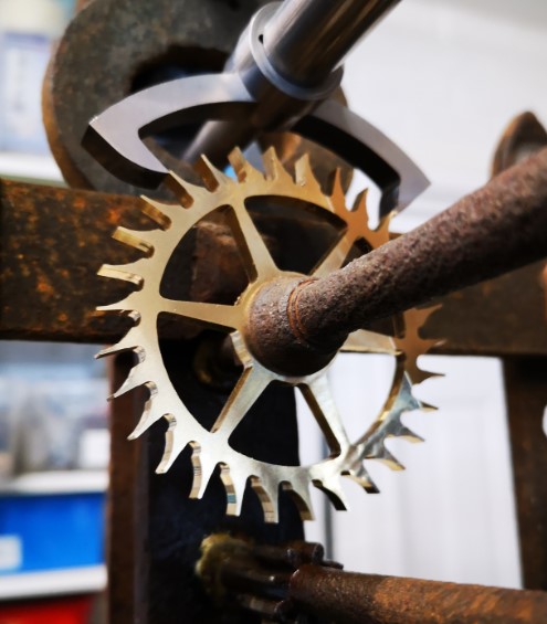
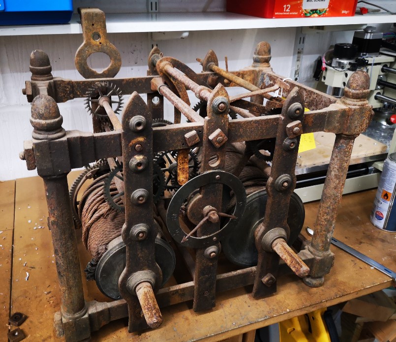
I am currently creating missing components for a Thwaites turret clock.  I had finished the pallets and I now moved onto the new escape wheel.   The design was created in Fusion 360 and integrated the pallets and the escape wheel together so the critical geometry was compatible.

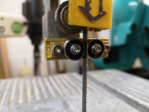
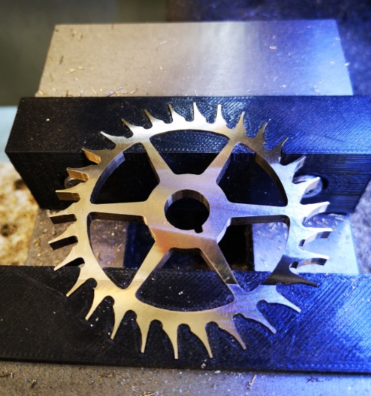
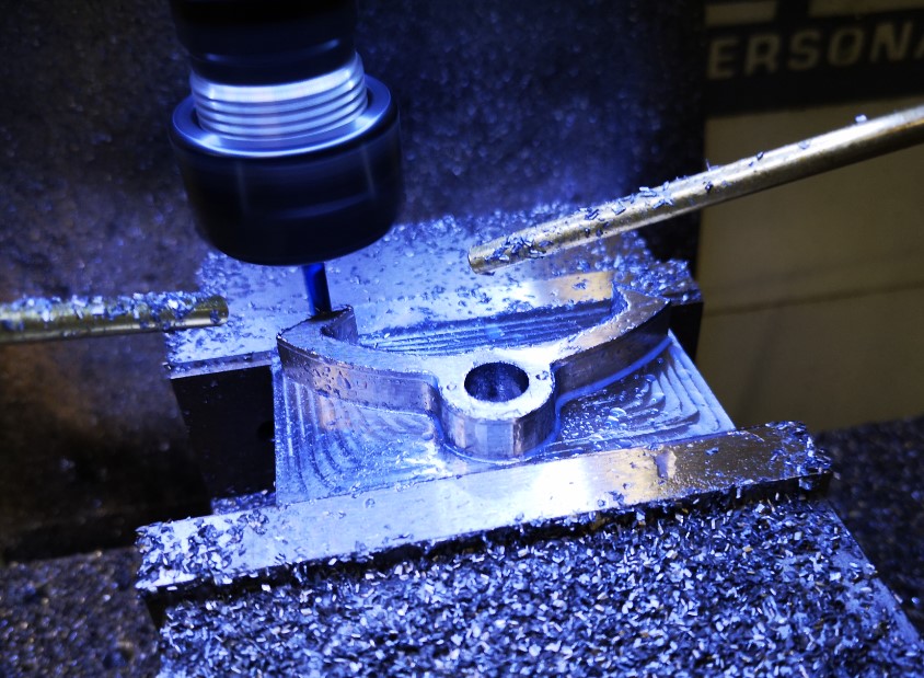
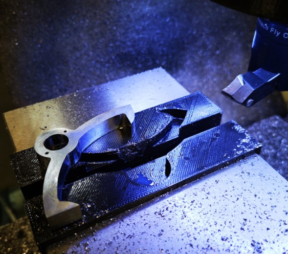
The brass blank for the escape wheel was a 1/4″ brass block which I managed to hold tightly in the machine vice with a 1mm thickness of gripping stock.  (I don’t have Tallon grips or similar so I have to be generous).  I machined the wheel and was left with this 1mm to skim off the reverse side of the wheel.

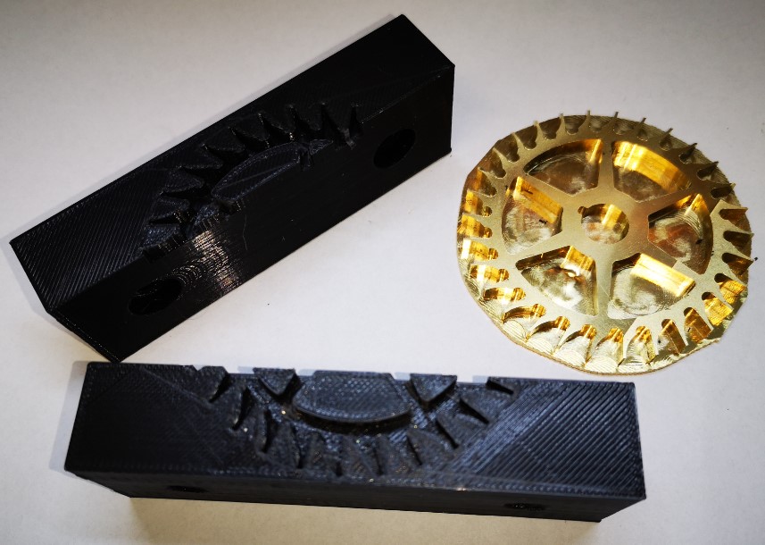
I did not want the teeth on the new wheel to get damaged when gripped in the vice so the 3D printed soft jaw concept appealed.   The PLA would provide grip.   The teeth on the wheel could bite into the PLA without suffering any damage.

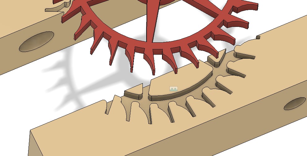
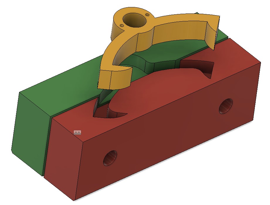
I had already created a single blank soft jaw In Fusion 360 for the previous pallet holding job.   This like it would be fine to accommodate the wheel dimensions.   I simply had to import two of these into the new soft jaw design (not forgetting to ‘Break the Link’ so the jaw models could be edited). I projected the wheel onto the soft jaw’s face and added a 0.2mm positive offset border.   I almost made the mistake of forgetting to invert the wheel as the soft jaw image must be a mirror of the Fusion top side view of the design to be gripped.

Fusion 360 view of the Thwaites wheel projected onto the PLA 3D printed soft jaws
Fusion 360 view of the Thwaites wheel projected onto the PLA 3D printed soft jaws.

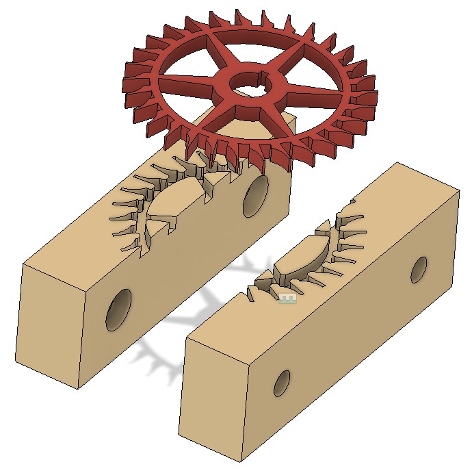
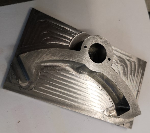
The finished brass wheel did not accurately reflect the geometry of the Fusion design.  This is because the resolution of the tight corner CNC operations were limited to tool sizes.   I added fillets to all the ‘sharp’ edges in the soft jaw image to accommodate this.   I also had to do some tweaking of the inter jaw spacing 3D joint to reflect the wheel diameter and the amount of grip I judged might be needed.

Close up view of the fillet modifications to the sharp corners of the wheel outline
Close up view of the fillet modifications to the projected sharp corners of the wheel outline into the soft jaws.
Soft jaws and wheel ready to be skimmed
Soft jaws and the brass wheel ready to be skimmed.   The residual original square stock has been roughly trimmed around the wheel circumference.
The jaws were printed and I have to say were somewhat cosy tight around the wheel geometry.   When the jaws were mounted in the machine vice, the wheel was not going anywhere and the excess backing brass was skimmed off quickly and easily with no apparent movement of the wheel in the jaws.
Finished wheel mounted in the jaws after excess stock had been skimmed off
Finished wheel mounted in the jaws after the excess work holding stock had been skimmed off.
The finished escape wheel and pallets mounted in the Thwaites clock

I am really warming to this technique.   It is quick and easy to implement and any mistakes can be quickly rectified with a new 3D print without having to remake aluminium versions.  I like it and recommend it.

Similar or related subjects : – 

Vice soft jaws and then soft soft vice jaws

A Different Approach to Soft Jaws

A comment that I often make is about how having varied resources available to do a job creates on the one hand a quandary as to what route to take but on the other hand it can lead to a light bulb moment. Having a 3D printer available along side a CNC machine often creates this dilemma and often to advantage. 

Stick with me on this.

I am currently immersed in creating parts for an old turret (church) clock as pictured below.   My wife put it down as a JSN job but once again the challenge it presented won the day.  

view of the church clock as delivered to me to work on
Not a pretty sight but things do seem to move and things are certainly missing.

The client found me from my blog entry about creating the Brocot wheel in CNC.   His clock as you can see is missing the pallet arbor, pallets, crutch and arbor suspension bracket.  If that wasn’t enough it also needs a new escape wheel.  This is very similar to the aforementioned Brocot wheel but smaller in size.  Fortunately the old escape wheel was still in place but in poor shape with the teeth ends fairly battered and one tooth partially missing.

I created the CAM for the new escape wheel in Fusion 360 and then from the wheel design created the geometry for the pallets.  (There is a great document created by the BHI as part of their DLC called ‘Drawing Clock and Watch Escapements’ that helped on this as did W.J. Gazeley’s book ‘Clock and Watch Escapements’). In order to check the pallet design I decided to first of all print a 3D model.   The printed part looked like it would work when tried against the original battered escape wheel.

Next step in my evolutionary process was to make an aluminium version on the Tormach CNC.   I used a superglue mounting block and cut the pallet profile for the full 10mm stock depth and down to the blue mounting masking tape.   Because the aluminium was so soft and I kept the DOC gentle this turned out well.

Although the aluminium version worked very well and helped me prove the working of the clock,  aluminium is too soft for clock pallets.   A steel set would now needed and I opted for 20mm ground flat stock as the ideal material.  

Side #1 was cut while being held in the machine vice on parallels.  A 2mm thickness of stock was left as the gripping layer.   All went to plan.

running side 1 of the clock pallets designed in fusion 360 and running on the Tormach 440 CNC mill
Side one machining of the clock pallet. An 8mm 3D Adaptive has completed and a 4mm follow on is now being run to clean up the finish.  Note the newly installed second Fogbuster nozzle.
Side one of the clock pallets completed showing the residual stock to leave as a side two operation
Finished side 1 operations and ready to invert to remove the residual stock used to grip in the vice jaws

Side #2 now became the headache.   I could have used the super glue bonding of the stock as per the aluminium version. My twitch was that this would leave very little of the pallet material remaining to act as a secure bonding face with the superglue.  Given I was cutting steel there was every chance of things parting company.  I could hold the model inverted in the vice but there was a real danger of the nib tips getting crushed.   Not a good idea.

Clearly the right solution was to make a pair of soft jaws to grip the pallet shape while I was decking off the side #2 residual 2mm.

Now here is the light bulb moment.   I designed the soft jaws in Fusion so they would swap out the existing steel jaws on my machine vice.   This is a straightforward process using the Project function.   The best demo of this that I have seen is by Cough42 and is worth a watch.

pictorial view of the pallet soft jaws to allow side #2 material to be removed
The jazzed up Fusion view of the soft jaws (red and green) and the finished pallet shape that gets gripped in them.

I was about to order some aluminium stock to make the soft jaws when the 3D printer winked at me from the corner of the workshop.  Could I print the soft jaws on the printer and get enough grip to allow the last 2mm to be decked off ?  This had to be worth a try and had the advantage that I could be getting on with another of the clock components while they were printing.

Taking this route I decided I would need to modify the design in Fusion.   The 3D printer always leaves cavities a bit under size.  I used Fusion’s Offset Faces to increase the profile shape by 0.2mm all around.  I set the gap between the two jaws at 1mm.

Print time was around 2.5 hours for each each jaw.   With CAM and setup time, running them in aluminium would have been similar.   I gained the 5 hours to do something else.  (i.e. Drink tea watching the mill ….)

The idea worked.   The PLA tightly gripped the inverted Side #1 profile while I decked off the 2mm residual stock.  I didn’t go too aggressive on DOC.

finished pallets with PLA soft jaws
View of the finished pallets with the PLA soft jaws in the background mounted in the machine vice

 A set of PLA soft jaws – not a radical idea but food for thought.   

Aluminium soft jaws are essential if you are going to be undertaking detailed feature machining of Side #2 but if it is a simple decking skim then PLA would seem more than adequate.  Soft jaws are 1 off items dedicated to a particular part.   They are consumable as is the PLA but the PLA versions are overall quicker to produce.

This has been another situation where what would have been a no brainer ‘this is how we normally do this’ turned into a ‘how else could I do this with the resources at my disposal and make life easier ? ‘.  It is that lazy side of me shining through yet again …..   

Onwards to the next phase of the clock activity.

Similar or related subjects : –

Adding stepper motors to a Myford VMB manual milling machine

Myford VMB Manual Mill Conversion to Stepper Motor control

After many years of winding the Z axis up and down on my Myford VMB I have finally got around to fitting motor control and it is a joy to use.   I am however suffering from muscle wastage as a result.

stepper motor control of a VMB manual milling machine
A general view of the stepper motor control conversion of a VMB manual milling machine. Only the X and Z axis are completed so far. The control box is on the wall behind the mill and has the Shumatech DRO control panel mounted on the front panel.

I have done a write up for those who might want to also enjoy a less taxing movement of X, Y or Z axis on their manual milling machine.  Click on the link below to download as a pdf.

 Fitting XYZ motor feeds to Myford VMB v4

Similar or related subjects : –

BK3 Replacement Drive Wheel

Final Push on the BK3 Bandsaw Upgrade

Having solved the BK3 motor drive pulley replacement my attention turned to the large drive wheel replacement.

My initial tack was to create a 3D printed version.   As I wanted to include the high speed option this needed a 24 tooth 5mm pitch pulley included.   This did not print well.   

Plan B was to buy a standard Bearing Boys 24 tooth pulley and incorporate this into the large diameter wheel. I modelled this in Fusion and concluded that perhaps a CNC aluminium part would be better.   This would allow undercutting of the underside face of the pulley.  This would not be possible using 3D printing as this would not be a supported area.

The stub axle that the pulley would revolve on protrudes 25.5mm from the BK3 side wall.   The blade wheel groove needed to be 10.25 wide to accommodate the belt width.  The retaining side walls needed to be 1.5mm wide.  This totals 13.5mm width for the large pulley leaving only 12mm for the small pulley that would be needed for the highspeed set up.

This now became complicated in that the large wheel needed to sit around 5mm from the side wall to keep the belt in line with the motor drive pulley.  A spacer washer was made for this. This left only 7mm width for the high speed belt and I needed at least 9.25mm just for the belt without retaining side flanges.

The light bulb moment was to realise that the high speed pulley could protrude beyond the stub axle without fouling the outer case cover.   I could use the full depth of the pulley and counter bore the front face sufficiently  to allow the axial retaining screw to hold the pulley assembly in place and allow free movement. 

Here is a very much simplified sketch of the final assembly showing the counterbore for the retaining screw and the counterbore for the pulley boss into the large wheel.   The small pulley and large wheel are locked together with 3 off radially spaced M3 x 10mm countersink head screws.

Simplfied sketch of final wheel assembly
Simplified sketch of the final assembly of the large wheel on the BK3. Profiling of the wheel internal area is not shown but see Fusion image below for these aspects.

Here is a Fusion 360 graphic of the final pairing of the 24 tooth commercial pulley and the CNC machined large wheel.   With hindsight the large pulley could be 3D printed by leaving the rear face completely flat rather than having a profile like the front face.

Parts needed to be bought in were obtained from Bearing Boys as follows : –

14-5M-25 (14 tooth, 5mm pitch,25mm tooth width) for the motor drive pulley.

24-5m-09 (24 tooth, 5mm pitch, 9mm tooth width) for the high speed pulley.

300-5M-09 (300mm, 5mm pitch, 9mm wide) 60 tooth belt for high speed operation

525-5M-09 (525mm, 5mm pitch, 9mm wide) 105 tooth belt for low speed operation

Note that all pulley and belt parts are to the HTD standard profile.

Here is the wheel in place with the belt set to run in high speed mode.

Replacement blade drive pulley with high speed pulley option
Replacement blade drive pulley with high speed option selected using the small 24 teeth pulley driven from the 14 tooth motor drive pulley.

Note that I had one additional issue to address.   

The aluminium wheel tended to not hold the blade centrally in the blade groove with the result that the teeth of the blade would rub against the wheel front flange.   This did not happen in low speed mode when the blade runs on top of the drive belt.   My solution was to fit a 160mm x 10mm wide elastic band in the wheel groove only when in high speed mode.   The particular elastic bands are a standard size from Amazon and others.   This solved the problem.  There is no abrasive impact on the elastic band so life expectancy should be high and replacements are very low cost.

The above drive modifications in addition to the modified blade guide that I have detailed elsewhere, have given my BK3 not just a new lease of life but also a more accurate cutting capability.   The effort has been more than  rewarded and is to be recommended.  

I have created a summary compendium of all the BK3 mods and additions that can be downloaded as a ZIP file on the link below.

ZIP file download link for BK3 Modifications v2

Similar or related subjects : –

Burgess BK3 Bandsaw Disaster and Repair

Some pieces of workshop equipment generate a sentimental attraction that is hard to break.  One such piece of kit is my Burgess BK3 bandsaw which is ancient but has up to now worked reasonably well for my needs.   I bought it on EBay from an owner in Lancashire and remember a nice day trip to collect it.

It is a very useful machine and gets pressed into use day in and day out.   That is until the other day when the blade came off with a loud twang.  On inspection the drive wheel had lost part of its blade outer retaining flange.   It appeared to be very old brittle plastic and the damage was really to be expected given the vintage of the device.

After head scratching I designed a replacement edging strip in Fusion 360 which I 3D printed and glued in place.   Fingers crossed that will give the machine a reprieve and extend its life.

In the course of looking for possible spares (no chance) I came across a reference to modifications to the BK3 in Model Engineer to improve the blade tracking and speed settings. Here is a link to the articles  burgessbandsaw2.  I am indebted to the members of my local model engineering club who came up trumps with copies of these articles for me.

The guide modification consisted of replacing the two stud guides with ball bearings.  While the machine was in pieces it seemed like a good idea to implement this modification.  The Fusion 360 3D model is shown below. The blade is sandwiched between the two ball races and these can be slid in and out and then be fixed in place with the cap head screws once the correct location is found to guide the blade.

I drew the replacement guide block assembly in Fusion 360 and milled it on the Tormach CNC from brass.   The 1/2″ bearings came from BearingBoys.

All is now re-assembled and running really smoothly.  The blade prefers to run in straight lines which is a revelation.

Update :  Since this blog entry I have made other modifications to my BK3 and these are contained in this link BK3 Modifications v2.

Similar or related subjects : –

Verified by ExactMetrics