I am slowly building up to being able to cut wheels on the Tormach PCNC440 with two possible methods.
The first is using Gearwheel Designer which is mentioned elsewhere on my blog.
The second route is more conventional using a PP Thornton or similar cycloidal tooth cutter and a dividing device on a rotary table. This later method is how wheels are traditionally cut in a lathe and there is a lot of information available on this.
In order to use the cycloidal cutters I need some form of arbor to mount the cutter in the Tormach spindle. I could simply turn a piece of steel bar to suit and mount this in a ER collet in the spindle. The downside of this simple approach is that every time the arbor was fitted into a collet the cutter would be at a different height from the table. I really wanted something a bit more repeatable as the centre line of the rotary table will always be the same so why not the cutter centering.
When I ordered the Tormach PCNC440 I also ordered the Tormach small rotary saw arbor (which to date I have never used). Pondering this last night I sketched up an adapter in Fusion 360 to allow an involute cutter to be fastened to the end of the saw arbor.
This is shown below. 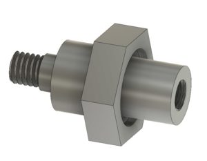 It is made from a piece of 19mm AF hexagonal steel bar with the hexagonal flats going to be used as a tightening it in place in the Tormach arbor. My Myford Super 7 when used with a 3 jaw self centering chuck is not bad on concentricity but for really accurate centering I swap the chuck for a collet face plate instead. This job was going to need both.
First operation was to turn the hex bar end that would screw into the arbor. This was done in the lathe chuck. It was a simple turn to a diameter and drill and tap the end with M6 to match the arbor mounting. The only pain was the arbor has a slightly protruding lip so I had to undercut the mounting face for this. Rather than trying to be clever I did it by hand using a graver.
While the hex stock was still in the lathe I roughly turned down the other end of the adapter to the primary diameter and slightly oversize for the cycloidal cutter bore diameter and then cut off the stock so far.
It would be important to get the cutter mounting running as square as possible so I swapped the lathe chuck for the collet plate and mounted the arbor end of the adapter in the collet. I carefully turned the shoulder for the cycloidal cutter diameter and then reduced the remaining length ready to cut a M6 thread.
Here are a couple of images of the finished adapter.

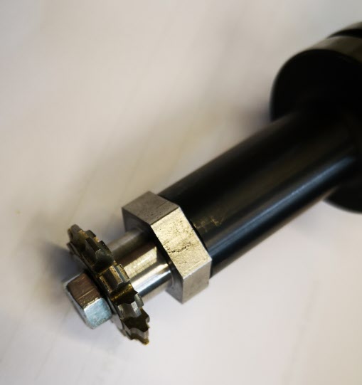
I am pleased to say the idea went almost to plan and it runs very true in the Tormach spindle.
I was a bit over enthusiastic with the graver but this is of no consequence.
With hindsight the shank between the cutter and the hex section ought to be longer as this will restrict the diameter of the wheel that can be cut before the blank catches the hex section peaks.
One step closer to trying this method. The next experiment is to work on a sub routine in GCode to move the cutter back and forth while cutting and with the ability to easily program the number of cuts.
Similar or related subjects : –
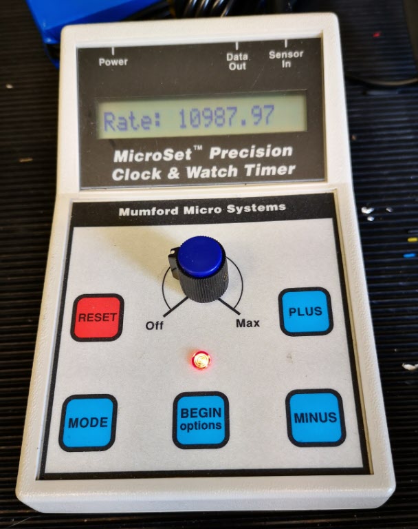
- Microset Timer interface using Fusion 360 3D model with Fusion Electrical
- Clock adjuster rod for measuring spring and fusee drive power
- Update notes on modifications to the Devon Sea Clock
- A church clock problem and lockdown timekeeping
- Repairs to an ancient Thwaites clock completed
- Further 3D printed soft jaws for the Thwaites clock escape wheel
- Vice soft jaws and then soft soft vice jaws
- Workshop resources all coming together like clockwork
- Making a Brocot Escape Wheel using Fusion 360 and Tormach PCNC440 CNC milling machine
- Silencing the Bill Smith Gearless Gravity Arm Clock