Mill Turning Jig

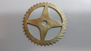
After a few distractions the Mill Turning Jigs are complete and I have run a test piece that is representative of a clock pillar.
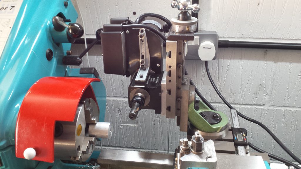
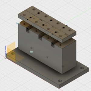
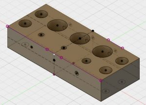
Mill Turning Jigs

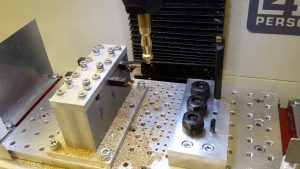
The jigs were both designed in Fusion 360.   One consists of a large block with space for three 10mm cross section carbide insert tools and a second block with drill and boring related tools.   I have fitted three ER16 collet chucks to this to allow flexibility of tooling choice.  Both have mountings to fit onto my 25mm hole matrix tooling plate on the Tormach.

The jig manufacture was relatively straightforward with the exception of needing a new 10mm end mill having extended length (35mm) to bottom out the ER16 collet mounting holes.   I got this from APT and the edges were lethally sharp.
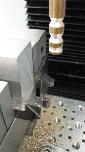
Design in Fusion 360
Mill Turning Lathe Tool Holding Block
Fusion 360 design
Mill Turning Drill and Boring Jig

Trial Clock Pillar

The pillar had simple geometry as below.

Simple Clock Pillar Trial Cut

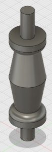
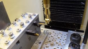
I opted to base this on  the largest pillar I had come across in any design which was formed on a 5/8″ brass rod.   I held the stock in the spindle in a 16mm ER32 collet held in a TTS holder.

I struggled a bit with the CAM for the trial as the tool geometry of the tools  I recently received from Banggood were not in the standard tool library.   I got some of the settings wrong.  That aside the result of the first run is quite pleasing.

My feeds and speeds were a bit coarse and I cringed once or twice at the tortured sound of brass under pressure.   I didn’t complete the parting off as I didn’t fancy ducking from a large piece of brass spinning lose at 5000 RPM.

Mill Turning Setup showing both Jigs in place
Zoomed view of Trial Cuts

As ever there was quite a bit of learning while making both the jigs and running the trial pillar test piece.

Drop me an email if you want more information !

Similar or related subjects : –

Mill Turning on the Tormach PCNC440

I just dared to hit run on my first attempt at Mill Turning.  I need to qualify this in that the first run I was cutting air above the set up.   It looked OK so I put the real material in the spindle and I got a turned part as designed in Fusion 360.   I didn’t part it off and you can see the result below.

Mill Turning set up for first trial run

Mill Turning is where you place the material you want to shape (usually a rod of some kind) in the mill spindle instead of a milling tool.   The tools are mounted on the milling table (see above in the vice) and are completely stationary but move via the actions of the table in the X axis and the spindle in Z.   The software is conned into thinking the material is really a milling tool and that the tools are the material.

It has taken me the best part of a week to work out how to model this in Fusion 360 and I have been helped enormously by watching Jason Hughes on YouTube.  It involves allocating a different Work Coordinate for the location of each tool.

If I can get this more streamlined and get some better lathe tooling in place to support it, then I will be able to turn clock pillars.   This was the last stumbling block in moving to CNC assisted clockmaking.

Tonight I am a very happy bunny.  A glass or two of Merlot with dinner perhaps ?

Update – For a full write up on the process and how I got there go to my mill turning page and download the pdf.

Similar or related subjects : –

Sherline Motor Assembly for clock wheel cutting

After completing the write up on the Sherline CNC Indexer for use on the Myford for clock wheel cutting, I realised that an important part of the process was the cutting mechanism itself.

I had adapted the Sherline headstock motor and spindle assembly to mount on the Myford vertical slide to act as a secondary cutting source. I use this for cutting clock teeth and for drilling holes ‘off centre’ to the lathe axis for such processes as arbor mounting holes.

The full write is available as a pdf on the associated page on this site.

Similar or related subjects : –

Sherline CNC Indexer on the Myford lathe

Some time ago I adapted a Sherline CNC Rotary Indexer to fit to my Myford Large Bore Super 7.   A recent request for details of how I did this has lead me to produce a write up for others to download.

Follow this link to the introduction page and download link.

Similar or related subjects : –

Ratchet Wheel Trial Cut using Gearwheel Designer

I am now running Version 21 of Gearwheel Designer and it gets better all the time.

I decided to make a ratchet wheel as my next test.  This highlighted the need to think about the process order on the mill.   Below is the design image in Gearwheel Designer.

My CNC sequence was as follows : –

  1. Cut the square brass blank a little oversize and draw a diagonals on it to show the nominal centre (Manual operation).
  2. Drill four holes in the corners outside of the working area of the cutting and use these holes to fasten down the blank to the milling table (which I had protected with a piece of MDF). (Manual operation)
  3. With a drill bit as appropriate, drill radial holes in the centre of the spoke petals and also the centre hole.
  4. Fasten the petals down to the MDF using these radial holes.
  5. Cut the gash outline of the wheel.
  6. Remove the four corner screws and remove the liberated brass outside the gash cut.
  7. Cut the rough pass on the teeth.
  8. Cut the fine cut on the teeth.
  9. Fasten down the periphery of the wheel with small clamps.
  10. Gash cut the spokes to leave the petals free from the blank.
  11. Remove the screws holding the petals and remove the brass liberated.
  12. Run the final cut on the spokes.
  13. Job done apart from a light sanding to remove any small burrs.

Some more images follow : –

Gash cut done and teeth cut twice round. The clamps are in place holding it down while the petals are cut.
Petals cut and removed for the final cut on the crossings
Finished wheel after a light papering

The purists will now tell me how it isn’t a proper wheel because the crossing interfaces to the rim have radius rather than a sharp corner.

Well a file will soon fix that …. and I can tell them how I watched another three episodes of House of Cards while this wheel was being cut.

Similar or related subjects : –

Verified by ExactMetrics