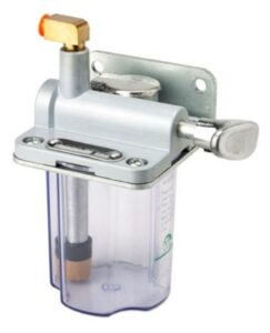
I have never been over the moon comfortable with the manual slideway oiler as supplied with my Tormach PCNC440. It has a hand pump that you pump once or twice and this fills a cylinder with oil. Inside the cylinder is a piston that empties the cylinder under pressure from a compressed spring. There are two O rings, one on the piston and one on the cylinder access end cap.
Original Tormach manual oiler
In the course of my ownership of the 440 I have had to replace the O ring on the cylinder a number of times. Once replaced the device works for a limited time and then fails again. The problem is made worse in that I can never find the right size O rings in the UK and have to resort to replacements from Tormach. These are not expensive but when added to carriage costs from the US it does become an issue.
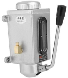
In frustration at the latest failure I found and bought in an alternative manual pump on Amazon. The action is slightly different in that pulling the pump handle action generates the pressure to feed the oil rather than leaving it to the spring return action. When the handle is released, the cylinder refills itself.
Replacement oiler which is available from a number of suppliers including Amazon
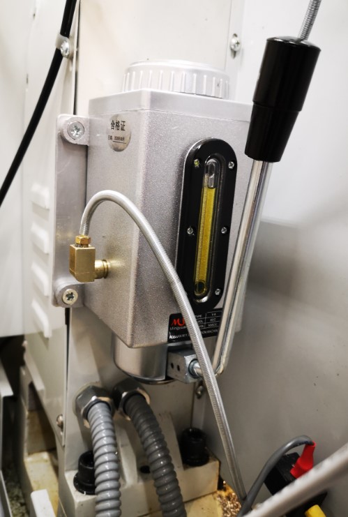
Physically the replacement device is slightly larger and I needed to make an adapter plate to fit it in the same position on the rear of the 440. The new device also has twin output feeds. This allowed me to replace the existing T splitter assembly with two separate feeds – one to the X and Y oil distribution manifold and one to the Z manifold.
Replacement oiler in place on the rear of the PCNC440
So far so good and it seems to push the oil out to all oiling points. Clearly this is something that has to be monitored or there is the danger of dry slideways and dry ball screws damaging the mill operation. I will report how the new style oiler performs longer term.
It has got me thinking that maybe using an Arduino I could create a ‘time to pump’ prompt beep at switch on and say after 4 hours of operation … a rainy day job ?
You know how I keep on going on about how solutions to problems are often solved by coming at them from different and often unconventional directions, by utilising and marrying available resources ? It was a philosophy that I encouraged in my team while running my business and it has carried over into my way of working in retirement. A recent job brought his home to me.
A client had a very old clock that had had a new barrel wheel made and fitted but the clock would not run for more than a few minutes. There appeared to be an incompatibility either between the modulus of the new wheel and its mating pinion or the shape of the original pinion did not match the shape of the new wheel.
If you spun the barrel wheel you could feel the resistance build up as the synchronisation between the two profiles drifted out. Adding extra weight to the barrel helped but did not solve the problem.
So what to do ?
The barrel wheel was serious engineering and I did not fancy making a new one. The existing mating pinion was a seven leaf format and its leaves were what you might call pear drop shaped rather than the expected profile. The pinion arbor had a 72 tooth wheel driving the next part of the clock train but we did have a spare one of these to hand from the minute dial.
Calculations from the geometry of the barrel wheel resulted in a modulus figure of 1.86. A rather large value and not one that conventional cutters are readily available for. The pinion was perhaps something that could be drawn in Fusion 360 and then made on my Tormach CNC PCNC440 milling machine. The only snag was that the profile needed on the pinion would likely be weird and the world’s supply of brass could diminish rapidly while getting the profile correct.
Using Gearwheel Designer I created what would be the expected profile for a 7 leaf pinion with a modulus of 1.86. This was exported as a DXF line drawing into Fusion 360. This outline was extruded in Fusion into a 3D design and a boss was added to mount the 72 tooth wheel.
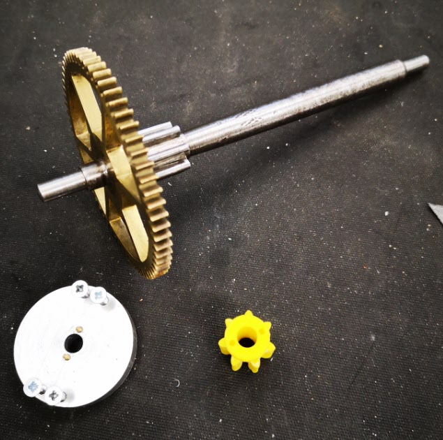
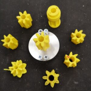
The design was 3D printed on my Sindoh 3DWOX printer and was mounted on a 6mm silver steel arbor. I added a driving disc that interlocked with the printed pinion and the crossings on the wheel to drive the assembly. Surprise surprise it didn’t run but it did mirror the regular pattern of stiffness of the original pinion.
The original arbor, pinion and wheel together with the driving disc and a 3D printed pinion test profile. The driving disc has screws to lock it to the wheel and two protruding pins to lock into the 3D printed pinion profile under test. The 3D printed profile was a tight pressure fit onto the new 6mm arbor.
I now had the test bed for quickly making and testing different pinion profiles. There followed a number of hours watching the engagement progression of the profile of the pinion into the barrel wheel and then trying to conceive a profile for the pinion that might run.
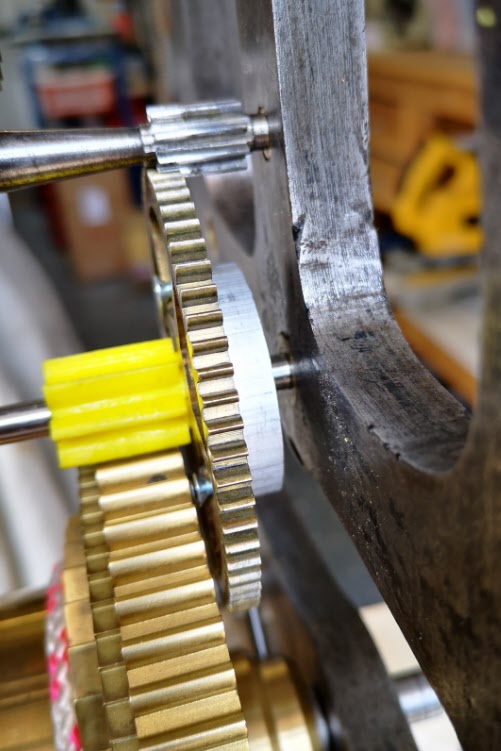
Various trial profiles and the temporary driving disc to engage with the 72 tooth wheel
A test pinion in place showing the 72 tooth wheel and the driving disc
Fusion 360 made this process so easy and round 10 printed test profiles later I had success with a clock that now ran. The driving weight on the barrel was around 11kg and it looked to be worthwhile wasting some brass making a ‘proper’ one.
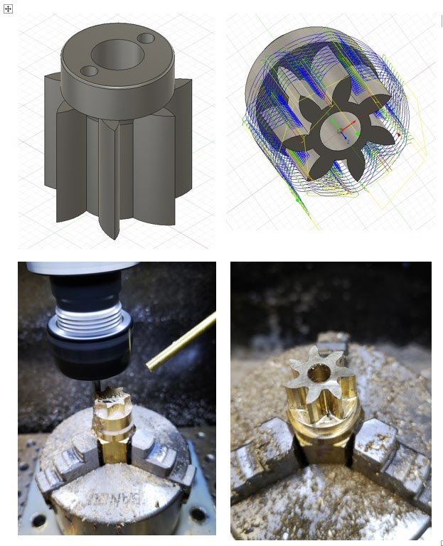
I took the 3D design and produced CAM code in Fusion. This would cut the profile ‘on end’ using an adaptive first cut with a 4mm end mill followed by rest machining the remaining material with a 2mm end mill.
The Fusion 3D model of the pinion, the CAM simulation of the leaf cutting, first adaptive cut of the leaves and rest machining final pinion
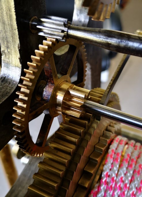
The resulting brass pinion was mounted on the arbor and the clock ran with a strong beat. As expected the brass pinion gave less surface to surface resistance than the 3D printed part and the barrel driving weight was now able to be reduced down to 6.25kg.
The finished pinion mounted in the clock on the new arbor
I ran my Microset Timer on the clock overnight and had a first off timing error of 5 minutes per day which was fixable with a pendulum tweak. The movement had an instability of a few seconds per day which was quite astonishing.
The conclusion of the experience is that at first glance this seemed like a conventional pinion cutting exercise …. but M1.86 cutters are not readily available. If a cutter could have been found at less than a King’s Ransom it is likely that the resulting conventional profile would have been wrong to match the barrel wheel.
The alternative route that was taken of Gearwheel Designer to Fusion to 3D print to Fusion CAM to CNC machining solved the problem albeit with a final weird profile. The purists and traditionalists will groan. There will be a gnashing of teeth and a pulling out of hair.
Does it really matter if the result is new life for what could have become a heap of scrap metal ?
I have been using a Wildhorse Innovation CNC set up probe for some time now. It works OK but sometimes the results are not consistent. After one frustration session I decided to upgrade it to the Hallmark ITTP probe from Threadexpress in New Zealand.
It arrived today after nearly a month in transit due to the current lock down restrictions. On opening the package I was impressed with the quality of the engineering. It is a nice device. It uses the usual 3 pronged contact mechanism. Supplied with the probe is a tube of grease that helps protect the contact reliability. The interface cable has a 5 pin DIN that plugs into the Tormach expansion socket and the shank is a standard TTS compatible size.
The Hallmark ITTP probe mounted in the Tormach ready for setup and testing. You can also see my angel ring light illuminator and Hall Effect tool height setter.
I ran through the initial preparatory procedure and then loaded it into the Tormach 440 spindle. Pathpilot has a number of excellent set up routines to adjust the probe and make measurements. One of these, the Effective Tip Diameter is quite critical. All this went to plan and very quickly. Some initial probing gave repeatable and accurate results so first impressions are good.
PathPilot probe setup screen and the two probing routine screens.
I’ll give some updates as the probe gets pressed into service but my first impressions are good with repeatable accurate readings.
In the course of checking out the ITTP probe I needed a reference cross check on the various setup measurements. My Haimer Taster seemed a bit erratic and on inspection I discovered the axial shank holding bolt had worked lose. This meant a re-calibration of the eccentricity of the probe point would be needed.
The alignment process involves adjustment of four grub screws in the shank body. These tweak the ’tilt’ of the shank to get a concentric rotation of the probe ball point. As there are four screws I use two hex Allen keys to make the adjustments to each in line pair. This is quicker than with a single hex key being swapped from side to side. It is a bit like the process I use when centring a 4 jaw chuck. The adjustment is done against a dial gauge riding against the probe ball point. Once you get the knack this process doesn’t usually take too long using the two key method.
The frustration is that the Allen keys provided with the Haimer are a bit chocolate based and the ends chew up easily. The result is you tighten a grub screw and the hex key end twists and gets jammed into the hex socket in the grub screw. While trying to waggle the jammed key you mess up your carefully made adjustment. Aaaargh !
I ground back the worn end of the Allen keys to clean up the hex profile but they quickly degraded. In the end I took the grub screws out completely and replaced them with some M4 cap head bolts. Joyful !
How ugly is this ? Replacement screws on my Haimer Taster
Yes I know it doesn’t look pretty but it is now a real pleasure to make the adjustments with a couple of larger T wrenches. It is probably a criminal thing to do to such a lovely instrument but life is too short.
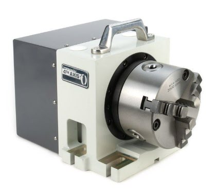
At last a 4th axis drive for the Tormach PCNC440 !
I have waited 4 years for this to be available and did not hesitate to put in my order to Tormach for one of the new MicroArc drives. Probably the best way to get a good idea of this product is to watch John Saunders’ video.
The MicroArc wasn’t a low cost buy and because 4th axis was not around when my 440 was originally shipped, I needed a fitting upgrade kit as part of the order. Having placed my order with Tormach it took exactly 7 days for DHL to arrive on my doorstep with the shipment. Quite amazing considering the difficult times we are experiencing at the moment.
It took me about one hour to fit the new stepper driver and additional wiring. As ever there were good clear instructions from Tormach. I switched on the 440, enabled the 4th axis in PathPilot and I could control the A axis from the PathPilot screen. Very impressed.
I watched John Saunders video on the MicroArc and how to do 4th axis programming in Fusion 360. I drew up a simple model in Fusion but could not get it to produce working GCode. I had some comms with John and he gave me some pointers. The model had a rotational repeat pattern but while I could run a single op code, if I tried to run the rotational pattern the post processor came up with an error message and would not output any code.
I thought at first it was because I was only using a Fusion hobbyist licence and that 4th axis maybe was not possible. A really helpful dialogue with Shannon McGarry at Fusion cleared up that issue so it must be something else.
After some experimenting I discovered that you have to set the axis of rotation in the post processor dialogue options list. All then worked fine.
My wife has presented me with a sign that has just got JSN written on it. It is to remind me when I answer the phone to a ‘can you just do’ enquiry…… to Just Say No.
I try my best to live up to her expectations but sometimes something comes along that should really be a JSN job but which scratches an itch. You know what I mean. You think about it and you do all the right mental arithmetic in your head and the answer keeps coming back to the same – don’t even think about it. But the the other side of my brain is screaming at me … what a challenge, what a learning experience, what fun to have a go at it. Providing the asking party is aware of your thought process or lack of it and accepts that it might just go belly up and never come to fruition then why not ?
Back to the story – 10 days or so ago I had a call from David Pawley who is a turret clock expert extraordinaire to say someone he knew was after an escape wheel for a turret clock and was desperate. David passed on the details and a couple of days later the potential customer arrived on our driveway. After a suitably socially distant conversation and a rubber gloves inspection of the old damaged wheel …. I got sucked in and turned the JSN sign over to face the wall.
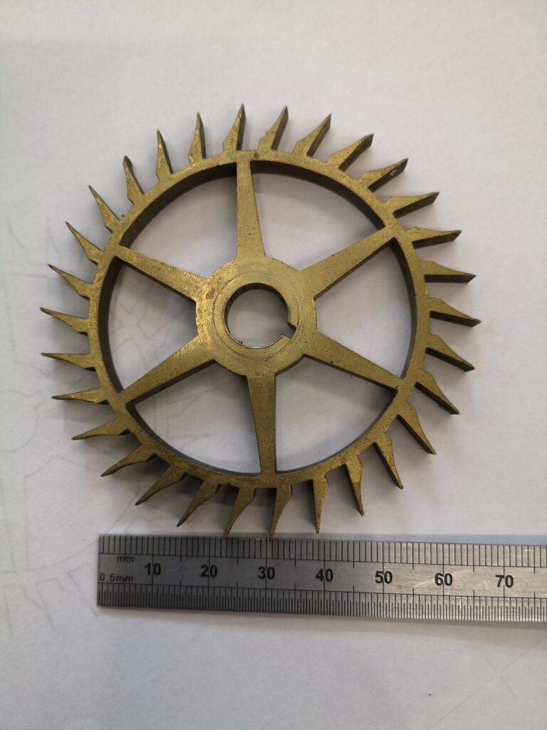
The original Brocot 30 tooth escape wheel that needed a new one making
As you can see it is not an ordinary escape wheel and I had to delve into one of my favourite books ‘Wheel and Pinion Cutting in Horology’ by J Malcolm Wild FBHI in order to learn about Brocot Escape wheels. Malcolm is a great guy and his book should be on any clock experimenters bookcase.
The Brocot is no ordinary escape wheel. In fact it is a real challenge. Not a simple fly cutter job. Traditionally it would be cut in an indexing device such as a lathe with two different cutters, one for the curve and one for the notch. I didn’t have these so I thought I would probably upset the traditionalists and try to use CNC.