After I decided to buy a Tormach milling machine I had debate whether to go for the 440 or the 770. This confusion was based on available workshop space and to a lesser extent on cost. I also did not have a feel for the total cost of not just the items I needed to buy but also what the total package would cost when it landed on my driveway. In the UK we pay VAT on not just the goods but also the delivery cost.
To help my thinking I put together a spreadsheet on Excel that split out the basic machine parts and then had a common section showing all the accessories I would need. This totaled everything up in USD and I then did a conversion to GBP at spot rate and then added VAT and duty factors for UK import.
This sheet helped my enormously and once I had all the key prices loaded from the Tormach site I could do ‘what if’ calculations to fit my budget.
I was recently contacted by another potential buyer of a Tormach and I sent him the sheet to help his thinking process. For anyone else thinking of buying either in the US or an overseas country I thought the sheet might help so I have spent some time cleaning it up and and I attach the new version below.
Simply put a quantity of each item in the column associated and see the impact of your shopping list at the bottom, either as a 440 or a 770. Clearly the sheet could be extended to a 1100 if that takes your fancy. (Don’t forget to check the current pricing from the Tormach site by searching on the product code shown on the sheet).
As part of my purchase package of the Tormach PCNC440 I ordered their granite block and height caliper. This meant I could measure and set tool heights directly into the tool table on PathPilot via the caliper USB connection. See the image below which shows the granite block, caliper and the associated dongle box.
This concept works really well and saves manual entry typo errors when measuring tool lengths. I have found one problem however and that is the caliper eats batteries at an alarming rate. These are CR2032 button cells which are not dramatically expensive, but the cost does start to add up. There is the added frustration of the caliper potentially not functioning at a critical moment when a new tool needs to be measured.
It struck me as strange that a device talking via USB should be dependent on a battery when 5V is available from the USB interface. The fact that this did not happen suggested to me that the connection from the interface box to the caliper did not have through continuity of the 5V supply. This wasn’t surprising given that the caliper runs from a 3V cell.
Investigation
I connected the caliper via a standard USB cable directly to a variable power supply connected onto the 5V power pin on the USB cable. Varying the power supply from 0V to 5V showed that the caliper would work quite reliably over a range of 3V to 3.8V but above this the display would blank or just show 8888 at high intensity so masking the actual reading.
I found a couple of 1N4148 signal diodes in my component stock and put them in series with the 5V feed from the power supply to act as a series voltage drop. This brought the working voltage delivered to the caliper back into the 3V to 3.8V range where it functioned without any problems.
Implementation
So the question was now as to how to implement this modification elegantly ? ….
Be warned that the modification to be described involves a change to the USB dongle box supplied with the caliper and as such will invalidate any warranty. Mimic what I did at your own risk.
The dongle box has four screws on the bottom cover and removing these reveals the controller pcb. Take care not to loose the three blue switch activator rods in the process. On inspection of the pcb, the USB cable entering the box has all four standard USB connections but the cable exiting to the caliper has the 5V lead (red) disconnected.
I found a pin quite close by to the output lead that was marked 5V. This was a possible feed for my two diodes. On measuring this I found it was at a lower voltage than expected suggesting that there was perhaps some circuitry between this point and the incoming 5V. I therefore chose to ignore this and looked instead to the input connection cable. I found the +5V connection (red) as it connected to the pcb. I connected the two diodes in series to this cable termination and then ran a connecting wire (orange below)across the board to the 5V output (red) cable which was previously not connected.
These modifications are shown below albeit with hot glue over the diodes and connections.
Modification to Tormach digital caliper dongle box
This completed the modification. I checked out all the voltages while the pcb was still outside the box and also checked the caliper was still working. I replaced the pcb back into the box and screwed the lid in place.
One final thing I did which is not necessarily essential but felt like a good thing to do, was to put a tantalum capacitor across the former battery contacts in the caliper battery compartment. This would act as decoupling should there be any ripple on the new supply to the caliper. See the image below. Note that the tantalum capacitor is polarised and its + lead goes to the former + battery contact (on the right as shown below).
While this is a potentially useful thing to do, it has the disadvantage that you cannot put a battery in the caliper if you want to use it ‘off line’ when not connected to a USB port. You could however plug it into USB charger via the dongle lead.
The other minor thing I did was to fit a small cable tie to retain the caliper connector in place as I found it easily become disconnected.
On putting the setup all back together, the caliper was working well with a nice contrast to the LCD display. Tool table updates work just as they did before so no issues there.
If you do this modification you might want to experiment with different diodes or the number of diodes needed to the drop the voltage from 5V to within the caliper normal voltage range. Note that you need to use small signal silicon diodes which will have around a 0.6V voltage drop per diode. Don’t use Schottky diodes as these generally have around 0.2V and so you would need at least 3 times as many to achieve the same overall voltage drop. You could try LEDs as they all seem to have different voltage drops but they tend to need a high drive current which if this is the case, makes them unsuitable for this application.
You could of course go really elegant and build a small integrated power supply chip into the dongle box such as the AMS1117. These are available in various fixed output voltages including a 3.3V version (which is popular for Arduino projects and available from Amazon). You can also buy a ready made 5V to 3V module based on the AMS1117 from Amazon. I like the AMS1117 and used the 1.5V version in my power supply modification to the Shumatech DRO systems.
Here is a printer friendly (and slightly updated) version of this article : –
The Tormach PCNC440 is a lovely machine and is more than big enough for my present needs. The one problem I had encountered was when coming to a tool change on a CNC job sometimes there was not enough Z height to get the TTS collet out of the spindle. This was particularly difficult when using larger diameter drill bits in a chuck style holder.
Once in program there did not seem to be any option to break the run and do a G30 or similar. What I really needed was a move of the spindle upwards and outwards to get it clear of the job and allow TTS access.
Reading up in Peter Smid’s excellent CNC Programming Handbook I could see that care was going to be needed to ensure that any movement was first of all a Z action and then X and Y to avoid the danger of crashing the tool into the job or its fixtures.
I had some discussion with John Saunders at NYC CNC and John was working on a video around this subject. He helped enormously.
The end result is to use G53 machine coordinates to first do a Z and then and X and Y to move the tool up and to the side for tool change access.
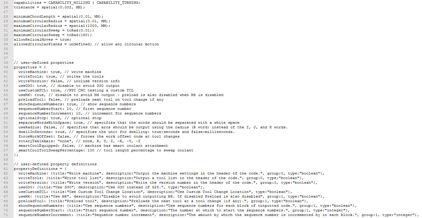
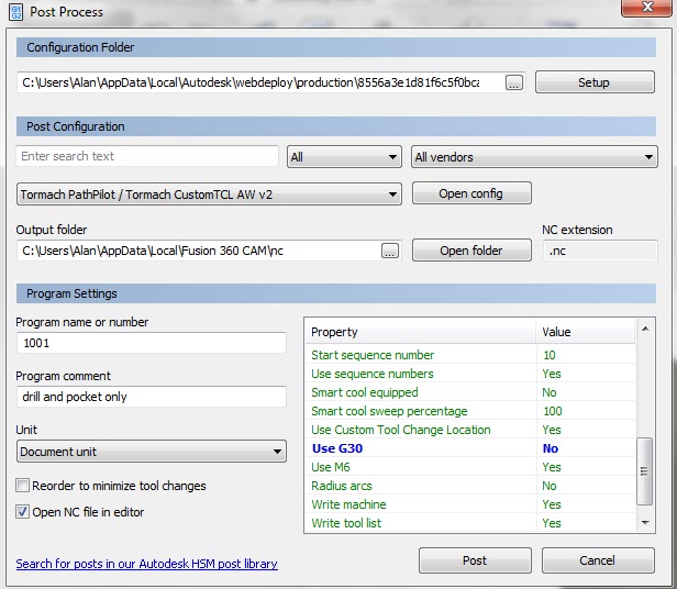
This involves edits to the post processor in three places. The first two edits (Lines 44 and 66) are there to give an option for this movement in the drop down selection box. (The line 24 edit is an earlier modification to allow Mill Turning – see separate post).
Line 24, 44, 66 editsChange that appears in the Property selection box where the Custom Tool Change option now appears
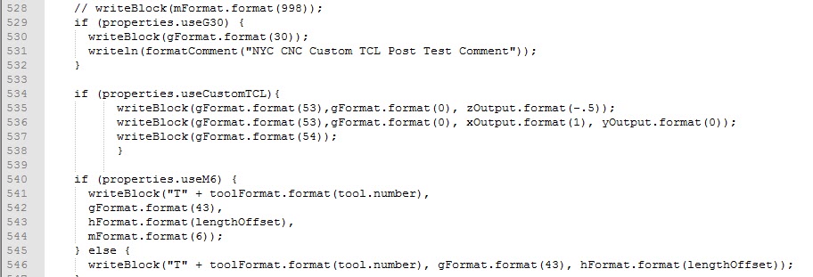
The third edit gives the instructions for this as a G53 Z move than a X and Y move (Lines 543-538). Note that I later found that I had to add a G54 after the G53 movements as some CAM actions did not include a G54 as part of a tool change.
Line 534 to 538 edits
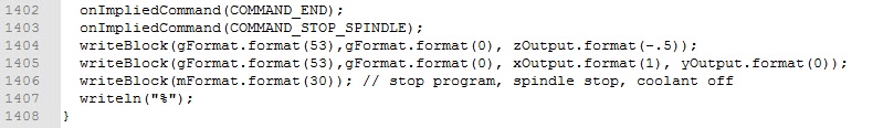
I later on decided it would be nice to include this G53 movement at program end so this is a fourth edit (Lines 1404 – 1405) and not forgetting the change for Mill Turning edit (Line 25) there are five changes in total.
If you can’t read the edits then drop me an email and I can send you a full listing.
Note that these are changes to the Tormach standard post processor code and if you are tempted to do this you should do a ‘Save As’ on the original code and only edit the newly created and saved file so you have a fall back position. Likewise I accept no responsibility in documenting this and putting you up to potential mischief messing with your machine and causing damage.
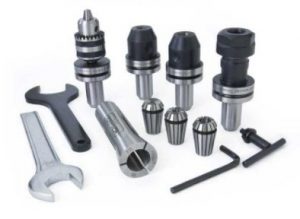
Tormach provide a rather nice tooling system for their milling machines. This is known as the TTS. There is a master collet permanently fitted in the spindle. If you have the automatic tool changer option fitted this collet is depressed by a compressed air driven ram. This opens its jaws to allow grabbing of individual sub collets holding the tool of choice.
The great bonus of this system is that you can have all your regular (and not so regular) tools permanently mounted in collets ready to go. Press the button driving the ram and push the next tool home. This also means you can populate the tool table in the PathPilot CNC driver program with all the tool length offsets without having to measure each time you do a setup.
It does mean quite an investment in the sub collets. These are available for all manner of capacities both metric and imperial either with fixed diameter grips or standard ER ranges. There are also custom tools such as the Super Fly and Shear Hog plus fittings to take a Haimer shank.
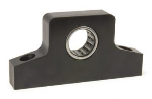
What was always a fiddly job was mounting a new tool in a collet and trying to contra-rotate the collet tightening nut while holding the body. This is now no more ….. I have just taken delivery of Tormach’s simple but elegant solution to this.
It is a ball race mounted in a block but a ball race that only rotates in one direction. You simply push the collet shank into the ball race and it is gripped tight. To loosen the collet you simply put it in from the other side. Magic !
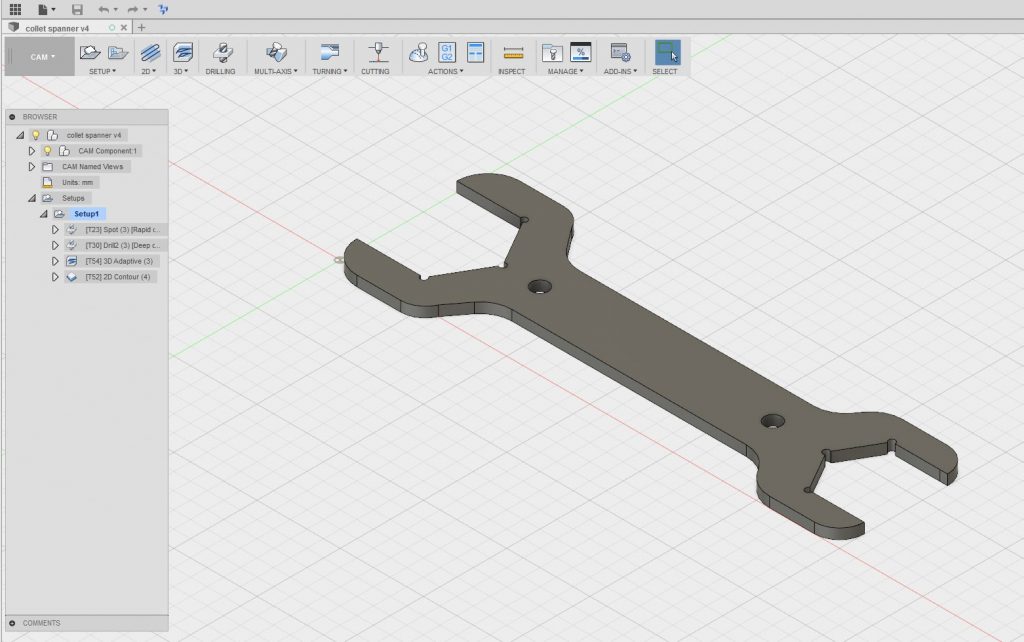
Now you have probably realised I am a bit OCD and like things in their place and ordered. Having got the tool gripping sorted I would now need two spanners to fit the collets of my most popular ER16 and ER20 nuts. That was one too many spanners for my liking and was tying up standard shop spanners (which also have their allocated place in the shop …. oh dear how sad is that).
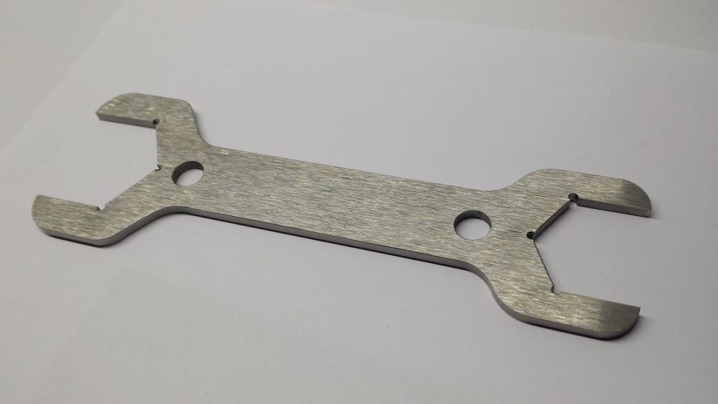
Now I happened to have a strip of 50mm wide Ground Flat Stock sat idle and Fusion 360 was calling. A quick drawing on Fusion delivered a customised spanner sized to suit the two most popular sizes of collet I use. I ran the CAM and off to the 440.
I put a piece 6mm hardboard on top of my tooling plate and put a couple of M8 holes at 75mm spacing on the centre line of the stock and fastened it down through the hardboard into the tooling plate on the 440 bed. I made sure the Z clearance was OK for the screw heads (important !) and hit go.
It was the first time I had machined GFS and the 440 handled it well. I now have a nice customised spanner hanging on the wall above that fancy bearing block.
Disclaimer : – This post and many others on my website feature references to Tormach and its products. I have no connection to Tormach Inc financially, commercially or otherwise. I acknowledge that Tormach®, Tormach Tooling System®, TTS® and PathPilot® are all registered trade marks of Tormach Inc.
I have made some good progress on taking a PCB design Gerber copper and Excellon drilling files into CNC. I think it is worthy of a full write up but while that gets put together here are some comments.
First of all the conversion process using FlatCAM is very straightforward and I like the fact that you can default save your GCode startup and end routines along with other default settings. Note that I had to scale the drilling data by a factor of 10. Apparently this is not unusual.
The fun starts once you have code ready to run on the CNC. The board design I was working on was a single sided copper design. Single sided board tends to always have a curvature with the copper on the inside of the curve and the fibre glass outside (if you see what I mean). This is probably the manufacturing process with the copper and its adhesive ‘pulling’ the board.
Double sided PCB tends not to be so bad in this respect and the effect is balanced out by the two coatings. My board was therefore much more bowed than a double sided one. (Incidentally FlatCAM allows for double sided board designs).
If you think about the geometry of what is going on it is critical to make sure the PCB material is flat on the milling table. The greater the included angle of the milling cutter tip the worse things get if there are variations in surface height. A height variation equates to a widening of the tool cut. See the image below. (Not to scale).
I initially used 6mm MDF as my sacrificial backing board to protect my tooling table. When I checked the MDF for flatness with my Haimer I was disappointed with the result. Increasing the MDF to 12mm made a huge difference and good enough for the purpose. This could have been a different manufactured MDF so the change of size is not definitive.
Initially I clamped the PCB to the MDF with a number of woodscrews around the periphery. On checking with the Haimer this was not good with visible variations that I could impact by pressing on the PCB surface.
Next step was to replace the woodscrews with strips of 10mm square aluminium with a 1.5mm step on one edge. These were screwed to the MDF on all 4 sides of the PCB blank and this dramatically improved the flatness to a point were it was adequate. Pressing the board surface did not change the Haimer readings.
Flatness having been solved I addressed the cutter problem. I had ordered some 10 degree included angle cutters from China but while they were in transit I got to talking with Think & Tinker in the US. They were incredibly helpful and suggested that I should consider a 60 degree included angle cutter with a 5 thou tip. They also suggested I try their lubrication to improve the cut quality and to also help protect the tool from wear. Their tools also come with a fixed collar which means you can change out the cutter without having to reset your Z zero.
This 60 degree cutter worked a treat and the results were startlingly good. I did not use the lubrication from T&T but instead used my normal FogBuster fluid (QualiChem ExtremeCut 250C) on a gentle repetitive puff. This seemed to work and kept the dust damped as well as improving the cut.
While I could run the spindle at up to 10,000 RPM, I kept it down at 6,000RPM with a cutting speed of 3″ per minute (75mm). I had a Z clearance of 0.1″ and depth of cut of 0.005″. (Sorry for the mixed dimension standards but PCBs tend to be designed in Imperial but I prefer to work in Metric).
After the milling of the copper was complete I drilled all holes at 0.6mm (24 thou) using a carbide drill sourced from Drill Services of Horley (UK). This was simply a change of tool, registering the tool length and loading the drilling GCode produced by FlatCAM. The drilled holes were spot on dead centre in the copper lands.
In closing I would like to say how impressed I have been with the Tormach. I had milled the copper one day and switched off for the night. Next day I switched on the mill and absolute referenced XYZ and put the drilling tool in the spindle and hit go. The holes were smack on dead centre in the lands without having to tweak anything.
It has been an interesting challenge that my friend had set me and he has gone away with a good looking PCB and my knowledge base has improved which is what it is all about.