Plastic heat sealer – a useful workshop asset

Clough42 has just posted making a protective cover for his plasma cutter control screen.   As ever with James it is engineering perfection with stitched corners.

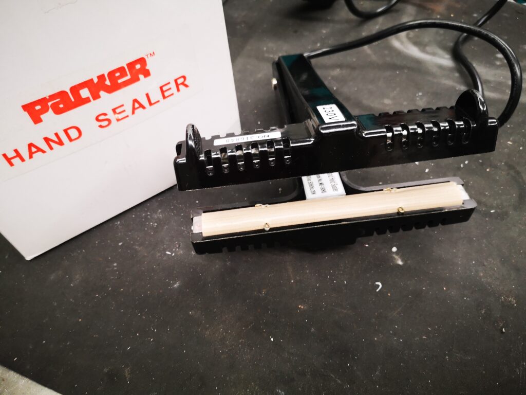
My lazy way (as ever) is to make such items using polythene plastic sheeting and a heat sealer. 

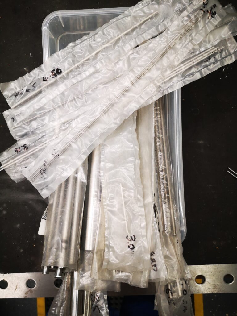
This allows me to quickly make bespoke covers and pockets for all manner of applications.  Here are a few examples.

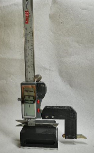
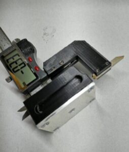
All my silver steel is stored in such pockets and has the size written on the sleeve using a Sharpie. 


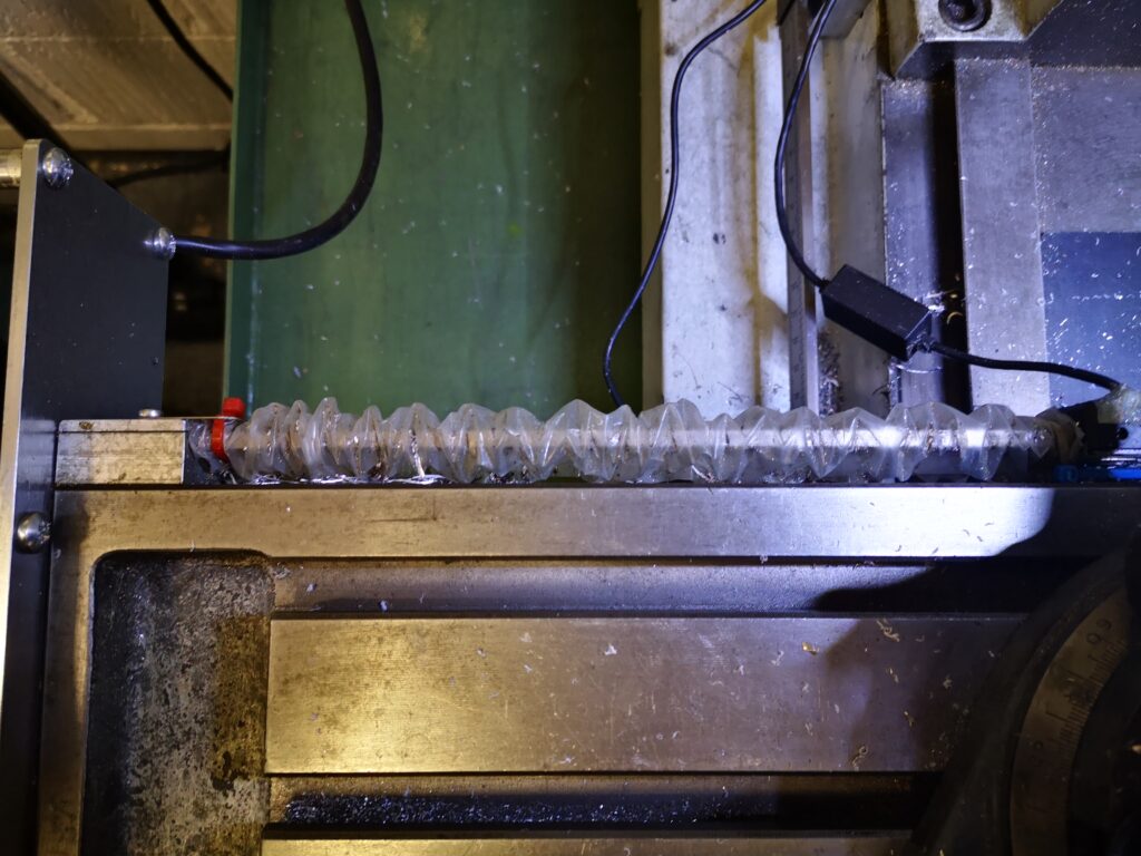
The rear DRO scale on my VMB has an open ended pocket either side of the vice that acts as a concertina cover to keep cutting oil from affecting the scale reader.

So another useful tool to have available (without having to thread a needle).

Similar or related subjects : –

Deburring techniques in the home workshop

I don’t know about you but deburring a job after machining I find to be a real pain.  This is an important process not just for the look of the finished product but also to give personal protection from the resulting post machining sharp edges.

If it is a CNC job then a small deburring chamfer can be added to the CAM operations but that may not be always possible to easily implement.

A manual deburrer such as made by Noga is another option but on a large geometry job it is difficult to get a uniform profile to the edge chamfers when done with such a manual tool.   Inevitably you occasionally slip and scar the surface of the job and this really irritates.

Noga Deburring Set
Noga Deburring Set with internal and external cone tools

I do like the cone shaped tool for deburring holes. Incidentally Banggood offer blades and handles that are identical and interchangeable with the Noga range including a series of different sizes of the cone tools.  Here are a couple of links to get you in the right direction but there are numerous sources of similar products.

https://www.directnine.uk/products/sp1010-trouble-shooter-set-noga?gclid=CjwKCAjwq7aGBhADEiwA6uGZp8hHRPi6XvgIS6EHCAYGTcIHZUcLzjPcJ1UPpydpJ7Wg8D7EWQW5yBoCocoQAvD_BwE

Banggood DrillPro Equivalent Set

My most recent revelation was to get a deburring wheel.   I bought this from Zoro Tools.   It is a 6″ diameter wheel made by Bibielle.  There are quite a few other sources of this type of wheel. I made an arbor to mount the wheel into my drill press.  Deburring wheels are meant to be mounted on a horizontal grinding machine but bench space is tight in my workshop so it has to be a drill press mount as and when needed.  I have to say this is a joy to use and gives a quick clean finish to all cut edges.   The wheel also gets used for surface cleaning on dirty materials.   A useful addition to the workshop and one I wish I had discovered sooner.

Similar or related subjects : –

3D printed multiple punch holding tool using Fusion 360 Parameters

Using Fusion 360 Parameter Functions on this useful tool

I was pointed to this punch holder idea by a friend.  It was shown on HomeMadeTools.net and conceived by Andy Foale.   

Here is the link to the original post : –

https://www.homemadetools.net/forum/multiple-hand-stamp-helping-hand-65882

I thought it might be practical to make it as a 3D printed device and with a bit of guesswork came up with a first pass design in Fusion 360.   This was based on my set of punches which are 6.4mm square (1/4″) and 58mm long.   The design printed in PLA without any problems and the finished punch holder worked fine.  It uses one of my printed knobs as mentioned in another post.

3D printed punch holder per Andy Foales
Fusion 360 pictorial view of the finished punch holder

The success led to requests from others who liked the 3D print concept but had different size punches so needed the design tweaked to suit.

This looked like a good excuse to re-familiarise myself with Fusion 360s Parameter functions.   In short these allow you to program interrelated dimensions in a design through a series of basic algebraic functions.   The end result is a design that is fully flexible on the size of the punches to be used and the number of punches that might be judged needed as the maximum ‘word’ length.

The Fusion file is here in a ZIP file

punch holder v5

The Fusion file includes the holder, the clamping bar and the knob body.   You will need a short length of M6 threaded rod and a M6 nut to finish the knob.  The file is configured to 6mm punches, 63mm long but you can edit using Parameters function under Modify.  Clearly once you have the Fusion file you could run also run a CAM program and CNC cut the punch holder.

I am afraid this is a Fusion 360 file only.   If you aren’t a Fusion user (why not ??) and you want a STEP file creating to your punch sizes then email me and I can run it for you.

As stated in the original article, the kerning of the letters is defined by the punch cross section.

Similar or related subjects : –

Kant Clamp and Engineering Drawings in Fusion 360

Bondie Hacks is a YouTube site that I have on my YouTube listing and a recent video featured Quinn building a Kant clamp from a kit.   Needing some lockdown distraction I decided that I would attempt to build a clamp from scratch.   Searching on Google revealed a plethora of drawings and from these I distilled a plan of action.

I created a Fusion 360 assembly for my hybrid version. The clamp was made with 3mm steel side plates and the other fittings from various diameters of silver steel.   From the Fusion drawings I created two CAM programs to profile the side plates and the other fittings were all straightforward lathe work with the exception of the gripping blocks.  I made these in aluminium which I ran freehand on my manual mill.   If the clamp is to be used for welding then it is traditional to make the clamps and the screw from copper.

I opted to fasten the side plates with screws and washers but the pillars could have been peened in place.   This would have made replacement of the gripping jaws difficult however so screws seemed like a better option. 

The result turned out very well and I was pleased that I had made the effort.

Stylised Fusion 360 model of my Kant clamp

I have produced engineering drawings on Fusion previously but all were a bit ad hoc.   Fusion is capable of automating the process of creating drawings for each component but I had never got to grips with it.   Having created the clamp I decided it was a good excuse to dig deeper into the drawing process.

There are various YouTube videos on creating Fusion engineering drawings but the one that helped the most was by Bryce at Autodesk.   The key to the automation process is creating Templates.   This is really worth watching if you are debating moving up a level with the quality of your engineering drawings.

https://www.youtube.com/watch?v=Av7rFL-opVo&ab_channel=AutodeskFusion360

The video goes into detail on how to create a customised set of drawing sheet blanks with customised title blocks.   Having watched this a couple of times the mists began to clear. 

The result of my labours is the complete drawing set for my Kant clamp in the following pdf file.   Feel free to download and build your own.

Kant Clamp Structure Drawing v9

Similar or related subjects : –

Converting a vernier to a height gauge using 3D printed parts.

Maybe not the full shilling but functional

This concept was passed to me from a friend and is based on a design published by Ralph Patterson in 2007.   The idea was to make a mounting block and extension arm in metal to allow a vernier to ‘stand up’ and be used vertically.   My contact sent me the drawings.  I don’t seem able to find any link to this or other files by Mr Patterson.

Entering the design into Fusion 360 did not take very long which indicates how well it was drawn originally by Mr Patterson.   There was one major modification however.   The original design was made from metal but our spin on it was to use 3D printed parts.   The base would therefore not have any really mass to keep it stable.   My friend suggested we added ballast in the form of lead shot into a cavity in the base.   I reduced the height of the base print by 3mm to allow an aluminium plate to be fitted to the bottom and added a honeycomb of holes into the base.   Once printed the honeycomb is filled with lead and the base screwed in place.   Conveniently and by fluke rather than design, the honeycomb holes will hold two slightly squashed 0.22″ air gun pellets.  This makes the base feel somewhat more solid on a surface plate.

The slot in the top of the base that takes the vernier is a tight fit on two of my verniers and the third one won’t fit so care is needed in choosing the right vernier for the job.   That aside it works very well for a quick and dirty measurements.

If anyone would like the STL files then let me know on the blog email or post a comment.

Similar or related subjects : –

Verified by ExactMetrics