

Oh No …… Not Another Spreadsheet …..
In the course of making miniature taper reamers to bore injector cones I initially struggled to set the compound slide angle sufficiently accurately. DAG Brown’s book details using geometry to set the angle and once I grasped this concept things improved. This is shown below and uses the Sine Rule.

The application method involves using a dial gauge set to zero when touched off on the workpiece. The cross slide readout is also zeroed at this position (this can be on a DRO if fitted or the Vernier scale). The compound is then moved a known distance along the workpiece before measuring the displacement needed on the cross slide to bring the dial gauge back to zero. Here is a picture. This is not rocket science and has been detailed on many other sources.
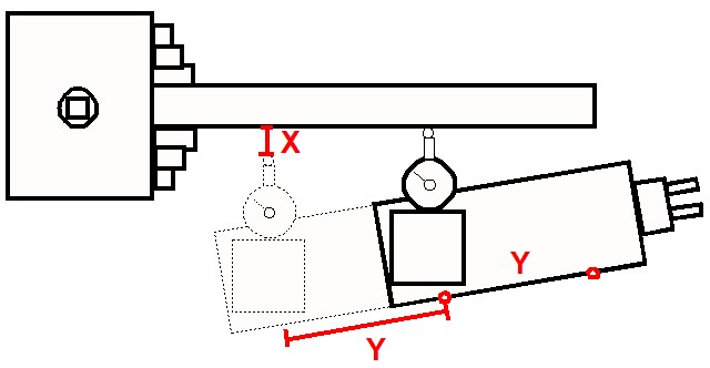
By making the Y distance as large as possible, the resolution of the angular setting will be improved. The distance for Y is best chosen to sit symmetrically either side of the ‘closed’ position of the compound. By standardising on a fixed Y distance the process can be made more repeatable for day to day use. Angles can be committed to a lookup table and hence my idea to create a spreadsheet as detailed below.
On my Myford Super 7 I decided that a distance of 50mm for Y gave me a reasonable travel distance (+/- 25mm on the closed position). This could be accurately measured using the compound Vernier scale dial (my Myford is a metric version).
To speed up the measurement process I scribed a 50mm spaced start and finish mark together with a datum mark on the side of the compound. The datum mark is on the protractor ring. These ‘scratchings’ are shown below. (The extra cap head screw and pin are the Geo Thomas ‘Red Book’ compound lock mods).

These markings remove the need to tediously count revolutions of the Vernier scale when making an angular measurement. I simply set the Vernier ring to zero at one mark and then keep winding the compound until the second mark is reached. I then check once again on the Vernier ring scale. The movement distance is then finely adjusted to zero by referencing to the Vernier ring scale zero. If you have a DRO on the compound this process becomes more flexible.
To mount the dial gauge I used my 3D printed gauge holder in the tool post.
With all the setup tasks decided, the spreadsheet was created. I chose to have 0.5 degree steps through to 69.5 degrees (it could be extended beyond this). I also added two standalone look up calculations. One to allow a single angle to be spontaneously calculated and one to back check a measured X distance to find its associated resulting angle. The latter would allow set up errors to be quantified to allow a knowledgeable ‘tap’ of the compound in the right direction.
The spreadsheet can use any units for Y as the table will automatically reflect this change. Here is a screenshot of the table based on my chosen value for Y of 50mm.

The spreadsheet .XLSX file can be downloaded from this link.
Accurately setting the compound slide angle
Similar or related subjects : –
- Dry lining wall fastener fixing aid
- Simple Vice tommy bar modification
- Soldering Iron bit storage on Lytool soldering station
- Water Softener goes AWOL
- Noga External Deburrer and Cut Screws
- Technoline Wireless Weather Station problem
- Using Raaco section boxes for fastener storage
- Bamboo barbeque sticks as dowels
- Spreadsheet Compendium by Popular Request
- Shopping list spreadsheet that has other uses