Technoline Wireless Weather Station problem

WS-2350 Poor Battery Life

I have had my WS-2350 Weather Station for a very long time and it has always worked reliably. The batteries recently died in the base station unit (3 x AA) and I replaced them. The unit sits in the kitchen and on entering the kitchen the following evening I noticed a glow coming from the LCD screen backlight LEDs. This was unusual as the LEDs should switch off after a few seconds of a key press. I didn’t think anymore about it and went to bed. Next morning the low battery symbol was showing…. and the LEDs were still dimly showing light.

I took the unit through to the workshop and powered it from a 6V external supply. Sure enough the LEDs were on and the current drawn was around 40mA, far too high for long life battery operation.

I removed the eight screws holding the case rear in place and struggled to remove it. There was a build up of corrosion around the battery contacts making them tight in the back cover moulding slots. Some careful cleaning eventually cleared this and the back cover came off. This revealed more accumulated ‘fur’ corrosion around the PCB lands holding the battery contacts and elsewhere on the board. This was cleaned off but the current drawn still remained high.

I next removed the PCB from inside the case. This needs six screws to be removed. A word of warning. These six screws while holding the board in place are also responsible for applying pressure to the conductive rubber contact strips that connect the LCD screen to the PCB. Be very careful not to disturb these strips. The board is also connected to the VLF rod antenna that receives the off air time code updates and also to the antenna for the radio transceiver that connects to the outdoor sensor module. Be very careful not to disturb these components.

I gently lifted the PCB out and sure enough there was even more corrosive fur on the back side of the PCB around the battery terminals and elsewhere on the board. I thoroughly cleaned all this off and with an abrasive pencil brightened up the the battery contacts.

After fastening the PCB back into the case, I powered it back up from the external supply. To my relief the LCD had re-connected okay and was fully working. More important was the power consumption had dropped to microamps. Problem solved. The corrosion somewhere on the board must have been creating a partial short across the PCB tracks. This must have been sufficient to make the processor think a key was still pressed and therefore the backlight LEDs needed to be held on.

As I had never had leaking batteries in the unit I would guess that there had been soldering flux left on the board when it was assembled and this had absorbed moisture and had ‘grown’ and become conductive over time.

I hope this helps someone who might be having similar problems. When battery powered devices are running with very low current it does not need much contamination between copper tracks to cause all sorts of weird effects.

Links to similar or related post are listed below : –

Using Raaco section boxes for fastener storage

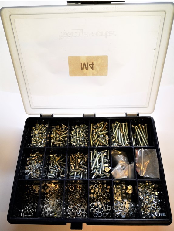
I am a great lover of the Raaco 18 section storage boxes for my various sizes and ranges of nut and bolt fasteners.   These boxes are not unduly expensive and are very durable with a sliding locking latch (assuming you don’t forget to slide it place – see below). 


To date these boxes have been stowed stacked one of top of the other on the shelf above my office workbench.   Come the need to get a particular size fastener for a job I can bet on the box I need to access being at the bottom of the stack.   This can get frustrating and can also be risky because if I haven’t fastened the lid properly there is an ever present possibility of a lot of fasteners hitting the floor with some associated colourful expletives.

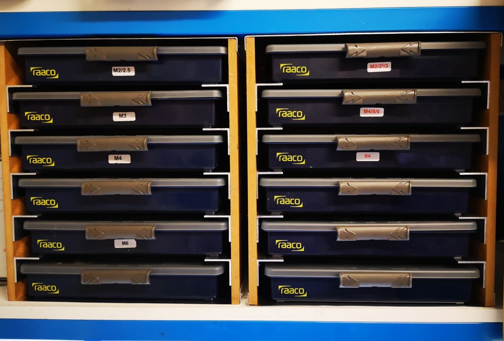
As you have probably gathered from the previous post, this has been woodwork week or at least MDF week if that counts as real woodworking.  After finishing the storage box for my clock bushing gizzmo I still had MDF to spare. With some judicious juggling in Fusion 360, I came up with a design for a slide in storage rack for my Raaco box collection.   In fact there was enough MDF left over to make two of these.   I did have to buy in some 30mm x 2mm angle though. The design allows access to any fastener box without the need to shuffle the stack to get at the one I needed.  Joy of joys.

The storage unit is 300mm high and has MDF sides and back board.  I had to revert to a 1mm sheet of  aluminium for the top and bottom surfaces to get the optimum number of boxes to fit between the workshop shelves.   Each storage slot has an aperture of 250mm x 47mm (excluding the aluminium angle) and is 180mm deep.

The added bonus to the design is that the Raaco fastener slide is a very tactile grab handle to draw the wanted box out of the rack.  The feel of the slide also acts as a warning flag that the slide might not be correctly locked in place.

Yes I know it is all a bit anal.   Making things to make things etc but less frustration means more productivity … well that’s the theory.

Similar or related subjects : –

Bamboo barbeque sticks as dowels

OK so this is nothing radical but worth adding to the armoury.  

I am in the process of making a protective box for my clock bushing tool and the various accessories that are used with it.   I had some 9mm MDF board in stock that looked a potential candidate for this.   The only problem with a 9mm board thickness is that this didn’t leave much margin for error using standard 6mm dowels and I did not want to use screws or nails to hold my box together.

The solution I came up with was to use 3mm bamboo barbeque sticks as dowel substitutes. These are incredibly strong in sub 25mm lengths.

I did cheat however and did not try fit them in blind holes but instead drilled the mounting holes through to the outside surface.   It still looks OK and has resulted in a very strong structure.

Using barbeque sticks as dowels
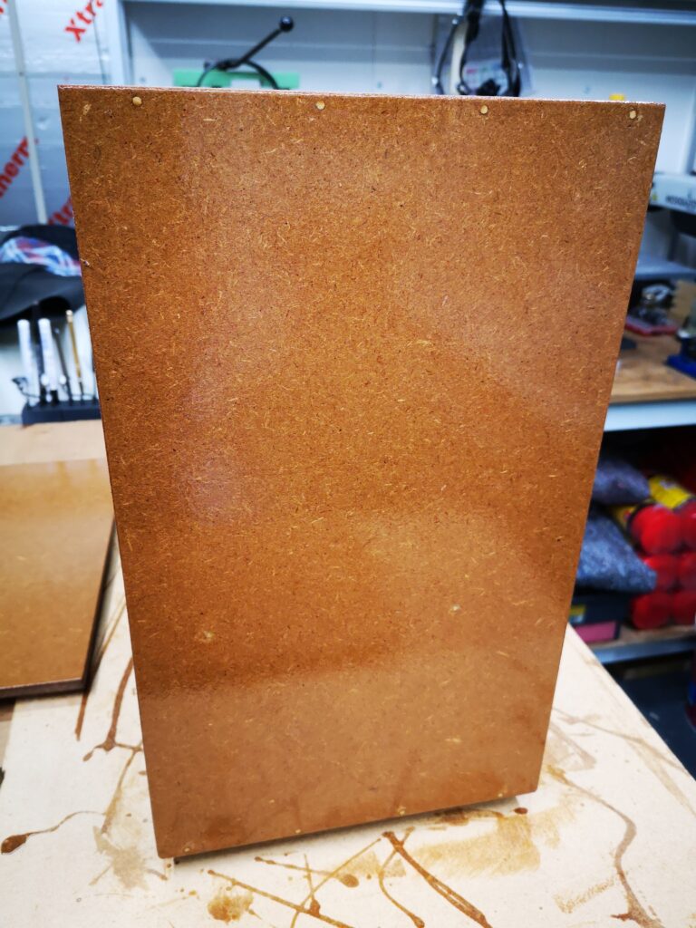
Image of the side panel of my home made clock bushing tool protective box. This shows the bamboo barbeque stick dowels bonding into the edge of the 9mm MDF components (the ‘dowels’ can be seen as white dots along the top and bottom edge).   The MDF is finished with Yachting Varnish.  You can see what a messy painter I am ….

Similar or related subjects : –

Spreadsheet Compendium by Popular Request

I have had a few requests for a compendium of all my spreadsheets created over the months and years.   This will be a work in progress as new sheets are created and then added.   Here are the current contents.   

A collection of my popular spreadsheets

Click on the link below to download the ZIP file.

Spreadsheets Compendium Jan 2022

Similar or related subjects : –

Spreadsheet for setting a lathe compound slide angle

Oh No …… Not Another Spreadsheet …..

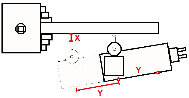
In the course of making miniature taper reamers to bore injector cones I initially struggled to set the compound slide angle sufficiently accurately.  DAG Brown’s book details using geometry to set the angle and once I grasped this concept things improved.  This is shown below and uses the Sine Rule.

The application method involves using a dial gauge set to zero when touched off on the workpiece. The cross slide readout is also zeroed at this position (this can be on a DRO if fitted or the Vernier scale). The compound is then moved a known distance along the workpiece before measuring the displacement needed on the cross slide to bring the dial gauge back to zero.   Here is a picture.  This is not rocket science and has been detailed on many other sources.

setting the compound angle using Sine Law
Graphical view of the setting technique.

By making the Y distance as large as possible, the resolution of the angular setting will be improved.   The distance for Y is best chosen to sit symmetrically either side of the ‘closed’ position of the compound. By standardising on a fixed Y distance the process can be made more repeatable for day to day use.  Angles can be committed to a lookup table and hence my idea to create a spreadsheet as detailed below.

On my Myford Super 7 I decided that a distance of 50mm for Y gave me a reasonable travel distance (+/- 25mm on the closed position).   This could be accurately measured using the compound Vernier scale dial (my Myford is a metric version).   

To speed up the measurement process I scribed a 50mm spaced start and finish mark together with a datum mark on the side of the compound.   The datum mark is on the protractor ring. These ‘scratchings’ are shown below.  (The extra cap head screw and pin are the Geo Thomas ‘Red Book’ compound lock mods).

These markings remove the need to tediously count revolutions of the Vernier scale when making an angular measurement.   I simply set the Vernier ring to zero at one mark and then keep winding the compound until the second mark is reached.  I then check once again on the Vernier ring scale. The movement distance is then finely adjusted to zero by referencing to the Vernier ring scale zero.  If you have a DRO on the compound this process becomes more flexible.

To mount the dial gauge I used my 3D printed gauge holder in the tool post.

With all the setup tasks decided, the spreadsheet was created.  I chose to have 0.5 degree steps through to 69.5 degrees (it could be extended beyond this).  I also added two standalone look up  calculations. One to allow a single angle to be spontaneously calculated and one to back check a measured X distance to find its associated resulting angle.  The latter would allow set up errors to be quantified to allow a knowledgeable ‘tap’ of the compound in the right direction.

The spreadsheet can use any units for Y as the table will automatically reflect this change.  Here is a screenshot of the table based on my chosen value for Y of 50mm.

The spreadsheet .XLSX file can be downloaded from this link.

Accurately setting the compound slide angle

Similar or related subjects : –

Verified by ExactMetrics