Replacement Cowells Chuck Key (Part 2)

Sintered Tool Steel Experiment

Some while ago I posted about my experiment in reproducing a Cowells ME lathe chuck key as it seemed there were a few owners with broken teeth on their keys.

Since then I have received a number of requests for replacement keys which I have tactfully declined.  They are not the easiest of things to reproduce and a potential for broken tooling.

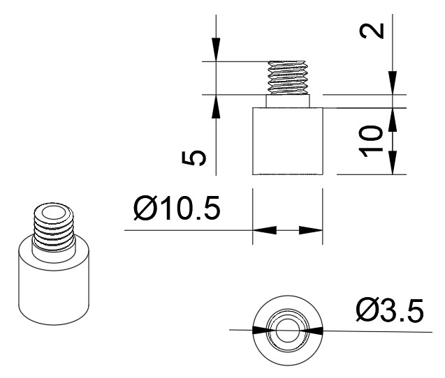
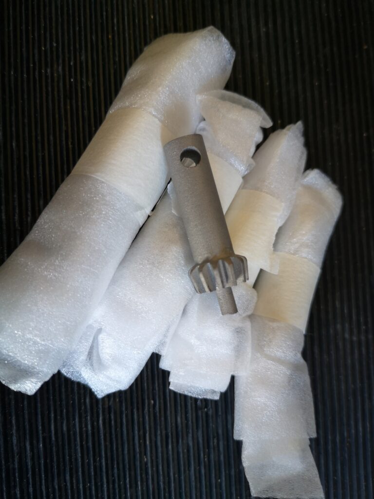
I use PCBWay for my production PCBs and I recently noticed that they can produce sintered 3D objects from a STL file.   They offer various materials for this process.  Out of curiosity I sent the STL file for the chuck key to them and ordered 5 pieces in sintered tool steel.  Twenty days later I received 5 chuck keys.   They look good and they match my dimensions and more to the point they work in the chuck.  I have no experience on how strong sintered tool steel might be but this video from My Tech Fun is quite impressive.

My Tech Fun

The downside of course is that they were not cheap (~£50 each, heavily thumped by courier costs) but if you have a Cowells and the frustration of a chuck key with a broken tooth maybe this is a reasonable price to pay.  Let me know quickly if you are interested in buying one otherwise I will put them on EBay.

Links to similar or related post are listed below : –

Illuminated Optical Centre Punch

A variation of a recently published design

There was a feature in a recent engineering forum by Nell’s Mechanical Man Cave regarding a 3D printed Optical Centre Punch.   The design had an angled magnified side window allowing the viewing of the punch point.  This conveniently allowed viewing of the point without having to swap out the viewer lens.

The author was offering a free download of the STL files for the punch body and also two versions of a base print.   I made contact and received the print files and duly printed out the body and base models.

To get a better understanding I suggest you view the YouTube post on the following link :

My immediate impression of the design was positive with the only drawback being the limited light available inside the punch body when trying to align the punch point.

I started a dialogue with Neil and suggested to him that the addition of LED lighting inside the punch body might solve this problem.  Neil was positive and supportive of the suggestion and the result is detailed below.

I re-modelled the punch in Fusion 360 and after some experimentation decided to mount two white light LEDs inside the dome of the body with the associated battery and switch mounted in the top surface of the body under a removeable cap.  Here are a couple of visual views out of Fusion.

You can download my full write up and updated STL files from the following ZIP file link.

Links to similar or related post are listed below : –

Gack Vice as a 3D Print

A possible light duty clamping solution

I came across the design of a Gack machine vice on a metalworking forum.   This is a two part vice that picks up on the tee slots in a mill table to allow an infinitely variable clamping width within the limits of the table dimensions.   It is ideal if a part needs to be skimmed flat over a wide area.   The item to be machined is clamped by an adjustable jaw against a fixed jaw and is supported by parallels as needed. 

The grip tightening adjustment is done with a ball bearing pushing centrally on the adjustable jaw with a M10 cap head screw and the gripping jaw hinges downwards on two dog point grub screws.  Here is an image of my interpretation of the concept. My aim was to create a vice that would be able to be mounted on my M8 tooling plate which has holes on a 25mm matrix or directly on the milling table tee slots which are spaced at 50mm.

I modelled my version in Fusion 360 and below is the Fusion exploded view.

The metal side plates are to increase the strength of the two hinging pivots of the clamping jaw.

The idea works well for light skimming jobs but would not be suitable for large depths of cut.

If you want a really robust version then you could replace the PLA print with a metal equivalent or you could buy a kit from Hemmingway Kits but their castings restrict the use to tee slot mounting only.

Click here to download a ZIP file containing my full write up, 2D drawings and the 3D STEP file.

UPDATE: – Since the original post I have updated the design to a totally metal version. The static jaw is now much easier to fabricate using a piece of angle plate. The mounting slot dimensions are specific to my M8 x 25mm matrix tooling plates.

Links to similar or related post are listed below : –

BK3 Bandsaw Lazy Susan Turntable Update

Adding a Rotation Stop Pin

There is no doubt that adding the Lazy Susan rotating base to my BK3 Burgess Bandsaw has been a good move. Being able to adjust the orientation of the BK3 to suit the material being cut makes life so much easier.

The one issue that has come to light is when adding heavy pressure to the cut I was having to push the material with one hand while trying to stop the BK3 rotating with the other hand/arm/knee.

Following one such episode I have added a stop pin that locates into preset holes in the new wooden base. I used one of the four unused holes in the original BK3 baseplate as the pin locating point. These holes are 6.5mm diameter (probably 1/4″ originally). I could have used a 6.5mm rod pushed through one of these holes into the new wooden baseplate but the BK3 baseplate metal is only 2mm thick. This would probably have resulted in a sloppy hold. Instead I made a small boss and fastened this into the BK3 baseplate left rear hole. The boss clamps on the underside of the baseplate and is held in place with a M6 nut and washer. The 3.5mm through hole provides a rigid guide for the locking pin. The sketch for the boss is below.

The four original holes in my baseplate were a bit rough and the one I chose to use needed a deburr so the shoulder on the boss sat flush to the bottom side of the BK3 baseplate.

The new wooden baseplate needs to be removed from the Lazy Susan so the boss can be mounted in place. Once the boss is in place the Lazy Susan is refitted. A 3.5mm rod is lightly hammered into the wooden baseplate to mark the desired lock positions. The Lazy Susan is then removed again and the wooden base drilled through at the marked locking positions.

The locking pin is a length of 3.5mm silver steel (drill rod) bent at right angles with its ends nicely rounded. The rod is ~45mm on the locating length and ~25mm for the grabbing handle. Here is an image of the finished construction.

This simple modification works extremely well and with hindsight should have been in my thinking when I first fitted the Lazy Susan.

Links to similar or related post are listed below : –

Noga Tool Christmas Present

Every workshop should have one

There was a recent thread on the MEW forum about Noga tools. It led me to download the Noga catalogue as a PDF. I am amazed at the technology that Noga produce to just remove burrs.

They are lovely tools and well worth the investment. I particularly like the external Rotodrive EX18 countersink. This is very handy for cleaning up the end of a newly threaded rod so the new thread will ‘take’. So quick and easy.

What really took my fancy in the catalogue on page 51 was this combination tool. That’s certainly one for my Christmas list.

No affiliation to Noga. I just like their technology.

“Better to have it and not need need it than to need it and not have it” – Jimmy Diresta.

Links to similar or related post are listed below : –

Verified by ExactMetrics