Burgess BK3 Final Modification – Lower Blade Guide
This is the final piece in my Burgess BK3 bandsaw upgrade jigsaw. Having successfully replaced the top guide with a double bearing assembly my attention turned to the lower guide. Using the same principle as the upper guide I came up with the following assembly.
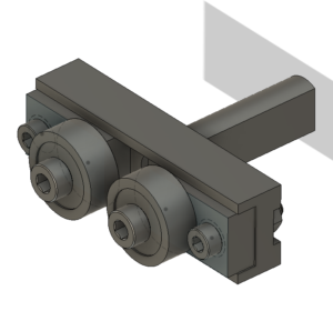
Stylised Fusion 360 image of the replacement lower guide assembly on my Burgess BK3 bandsaw
This seems to work well and is straightforward to implement. The bearings are standard 1/2″ size parts from Bearing Boys. These need a small brass bush to mount them on the sliding brass blocks. The blocks need a single M3 washer to space the bearing from the block and the body.
The blade pressure roller is made from silver steel and can be heat treated to improve wear from the blade edge.
The mounting bracket arm picks up on the original M5 mounting screw concept. The bracket could be milled onto the main body as a CNC operation but the two part assembly works fine and is very rigid in operation.
The link below is a complete set of notes and drawings pulled into one ZIP file to cover all the modifications I have done and separately document in my blog and other author’s notes that I have come across. I hope that helps.
My initial tack was to create a 3D printed version. As I wanted to include the high speed option this needed a 24 tooth 5mm pitch pulley included. This did not print well.
Plan B was to buy a standard Bearing Boys 24 tooth pulley and incorporate this into the large diameter wheel. I modelled this in Fusion and concluded that perhaps a CNC aluminium part would be better. This would allow undercutting of the underside face of the pulley. This would not be possible using 3D printing as this would not be a supported area.
The stub axle that the pulley would revolve on protrudes 25.5mm from the BK3 side wall. The blade wheel groove needed to be 10.25 wide to accommodate the belt width. The retaining side walls needed to be 1.5mm wide. This totals 13.5mm width for the large pulley leaving only 12mm for the small pulley that would be needed for the highspeed set up.
This now became complicated in that the large wheel needed to sit around 5mm from the side wall to keep the belt in line with the motor drive pulley. A spacer washer was made for this. This left only 7mm width for the high speed belt and I needed at least 9.25mm just for the belt without retaining side flanges.
The light bulb moment was to realise that the high speed pulley could protrude beyond the stub axle without fouling the outer case cover. I could use the full depth of the pulley and counter bore the front face sufficiently to allow the axial retaining screw to hold the pulley assembly in place and allow free movement.
Here is a very much simplified sketch of the final assembly showing the counterbore for the retaining screw and the counterbore for the pulley boss into the large wheel. The small pulley and large wheel are locked together with 3 off radially spaced M3 x 10mm countersink head screws.
Simplified sketch of the final assembly of the large wheel on the BK3. Profiling of the wheel internal area is not shown but see Fusion image below for these aspects.
Here is a Fusion 360 graphic of the final pairing of the 24 tooth commercial pulley and the CNC machined large wheel. With hindsight the large pulley could be 3D printed by leaving the rear face completely flat rather than having a profile like the front face.
Parts needed to be bought in were obtained from Bearing Boys as follows : –
14-5M-25 (14 tooth, 5mm pitch,25mm tooth width) for the motor drive pulley.
24-5m-09 (24 tooth, 5mm pitch, 9mm tooth width) for the high speed pulley.
300-5M-09 (300mm, 5mm pitch, 9mm wide) 60 tooth belt for high speed operation
525-5M-09 (525mm, 5mm pitch, 9mm wide) 105 tooth belt for low speed operation
Note that all pulley and belt parts are to the HTD standard profile.
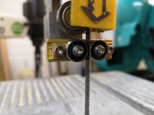
Here is the wheel in place with the belt set to run in high speed mode.
Replacement blade drive pulley with high speed option selected using the small 24 teeth pulley driven from the 14 tooth motor drive pulley.
Note that I had one additional issue to address.
The aluminium wheel tended to not hold the blade centrally in the blade groove with the result that the teeth of the blade would rub against the wheel front flange. This did not happen in low speed mode when the blade runs on top of the drive belt. My solution was to fit a 160mm x 10mm wide elastic band in the wheel groove only when in high speed mode. The particular elastic bands are a standard size from Amazon and others. This solved the problem. There is no abrasive impact on the elastic band so life expectancy should be high and replacements are very low cost.
The above drive modifications in addition to the modified blade guide that I have detailed elsewhere, have given my BK3 not just a new lease of life but also a more accurate cutting capability. The effort has been more than rewarded and is to be recommended.
I have created a summary compendium of all the BK3 mods and additions that can be downloaded as a ZIP file on the link below.
Since publishing details of the blade guide modifications on the Burgess BK3 bandsaw I have received a lot of interest and also a request for a replacement motor shaft pulley and a replacement blade drive pulley.
After dismantling my machine to check the dimensional details I discovered that the red plastic motor shaft drive pulley on my BK3 was severely worn to the extent of the teeth looking very distorted. (See image below). It would appear I need a new pulley also.
For those not familiar with the BK3 genre, the red drive wheel is a sliding fit on the motor shaft and has a helical slot in the end which locates into a cross pin through the motor shaft. The gear wheel is forced tight into the slot by virtue of the direction of rotation during cutting. Reading the handbook for the BK3 it seems that this pulley is designed to slide off to allow it to be swopped with an eccentric pulley mechanism when the BK3 is used as a fret saw.
The drive belt on the BK3 is 9mm wide and 5mm pitch (with 102 teeth). The red pulley has teeth extending axially over 25mm. This is to allow the one pulley on the motor shaft to drive two different pulley diameters on the blade drive pulley with only a change in belt length. This gives two blade speeds of 106m/min and 396m/min. My BK3 never had the second pulley combination when I bought it second hand. The BK3 is a well thought out machine and despite its vintage is very popular and commands relatively high prices on EBay etc.
Back to the plot.
My first instinct was to 3D print a replacement red pulley and this was successfully done using the Fusion 360 gear wheel design script. Rather than trying to model the helical slot I opted for a simpler solution of a pair of diametrically opposite ‘L’ slots. This worked well as a concept when trialled on the 3D printed version.
Rather than ship a PLA version to the client I opted to modify a standard off the shelf 14 tooth x 25mm wide x 5mm pitch pulley. These are available from Bearing Boys (14-5M-25). The one slight problem is that the boss on the pulley needs to be drilled out to 9.5mm to match the BK3 motor shaft. This does not leave a lot of meat on the boss. To get the best possible strength from such a modification I opted for a steel pulley rather than aluminium.
First operation is to drill out the centre bore of the pulley. The motor shaft appears to be 3/8″ (0.375″ or 9.5mm ish). I incrementally drilled the centre bore upwards from 5.5mm to 9.5mm but the pulley was still reluctant to slide onto the motor shaft. Not having an adjustable reamer I ended up using a letter ‘V’ drill to get a closer fit and then a light skim with a boring bar. After the shaft had been cleaned this combination gave a nice sliding fit
The red plastic pulley had a tooth width of 25mm. The teeth on the bought in steel pulley are wider (~28mm). The red pulley only has the single outside belt retaining collar. On this basis I gripped the boss end of the pulley in a collet and turned back the teeth width by 3mm. Note there is one slight problem. The belt retaining collars are not an integral part of the steel pulley casting but a thin dished additional fitment. The result is that at some point in the turning this fitment starts to rotate independently of the pulley body and I had to use the Dremel to cut this residual ring free before I could continue.
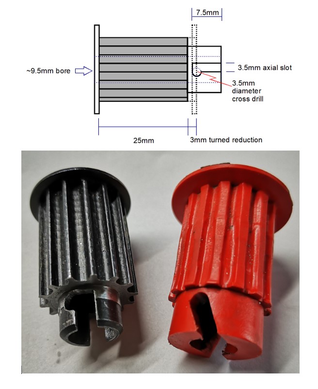
Having reduced the teeth width to 25mm, the ‘L’ slots need to be cut. I cross drilled the pulley boss with a 3.5mm hole. I then rotated the pulley in the mill jaws by a few degrees and then cut a diametric 3.5mm slot axially down to the same level as the 3.5mm hole and then hand filed the break through from the slot into the hole to create a retaining notch. The pulley bore was then cleared of any induced burrs.
The pulley now pushes onto the shaft and with a twist anticlockwise, the shaft cross pin locates into the ‘L’ slot notch.
Top image is a dimensional sketch of modifications to the standard off the shelf pulley. Lower image shows the new black pulley with a ‘L’ locking slot and the original red pulley. Note the wear on the original pulley and the helical locking slot.
So far so good. Next job is to recreate the large drive wheel pulley.
Some pieces of workshop equipment generate a sentimental attraction that is hard to break. One such piece of kit is my Burgess BK3 bandsaw which is ancient but has up to now worked reasonably well for my needs. I bought it on EBay from an owner in Lancashire and remember a nice day trip to collect it.
It is a very useful machine and gets pressed into use day in and day out. That is until the other day when the blade came off with a loud twang. On inspection the drive wheel had lost part of its blade outer retaining flange. It appeared to be very old brittle plastic and the damage was really to be expected given the vintage of the device.
After head scratching I designed a replacement edging strip in Fusion 360 which I 3D printed and glued in place. Fingers crossed that will give the machine a reprieve and extend its life.
In the course of looking for possible spares (no chance) I came across a reference to modifications to the BK3 in Model Engineer to improve the blade tracking and speed settings. Here is a link to the articles burgessbandsaw2. I am indebted to the members of my local model engineering club who came up trumps with copies of these articles for me.
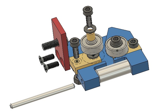
The guide modification consisted of replacing the two stud guides with ball bearings. While the machine was in pieces it seemed like a good idea to implement this modification. The Fusion 360 3D model is shown below. The blade is sandwiched between the two ball races and these can be slid in and out and then be fixed in place with the cap head screws once the correct location is found to guide the blade.
I drew the replacement guide block assembly in Fusion 360 and milled it on the Tormach CNC from brass. The 1/2″ bearings came from BearingBoys.
All is now re-assembled and running really smoothly. The blade prefers to run in straight lines which is a revelation.
Update : Since this blog entry I have made other modifications to my BK3 and these are contained in this link BK3 Modifications v2.


 With hindsight the large pulley could be 3D printed by leaving the rear face completely flat rather than having a profile like the front face.