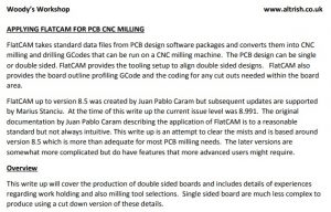
After a lot of editing I think the attached document will give an in depth understanding of how to use FlatCAM based on Version 8.5. The document is based on our experiences and a steep learning curve. We now have a repeatable process for milling PCBs from Gerber and Excellon files exported from a PCB design package.
The document may well have mistakes and we would appreciate feedback good or bad.
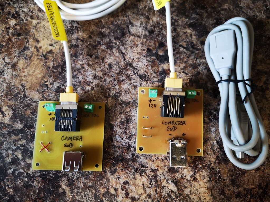
One of our group of ‘silver experimenters’ is building an Arduino based celestial camera tracker. This will be deployed in the garden and he needed all control to be routed back inside the house. The garden installation consists of a USB webcam mounted on a servo controlled platform all powered by 12V DC.
We pondered long on how we might remotely connect to the garden. The crucial thought was that the Arduino servo board was a two wire interface using the I2C format data exchange. Given that the USB needed four wires and the DC supply two wires we had a need for an eight core cable connection. It seemed like a length of CAT5 cable would do the job and we could elegantly use standard CAT5 sockets.
The PCB was designed in Design Spark and milled on the Tormach PCNC440 using FlatCAM.
There is a problem with running USB over more than 5m but I did some tests at 10m and all seemed fine which should be adequate for the application.
The breakout boards had a male and female USB connector fitted and the connections had to ‘cross over’ on one of the breakout boards to maintain continuity. We also paired the Data + and Data – connections with the +5 and Ground twisted pairs in the CAT5 so the Data + and Data – were not twinned together.
Nothing technically magic but a simple solution to a project need.
While I have been quiet for the last month or so there has been some intensive work by Dave and myself on FlatCAM. We are in the throes of doing a formal document to help others get to grips with the process and techniques for milling circuit boards.
I need to also put my hand up and admit going over to yet another dark side by experimenting with Arduino technology. This came about as a follow on to the work on silencing my Bill Smith Gravity Arm Gearless Clock. With the help of another colleague we have replaced the discrete timer logic board with an Arduino. I have learned quite a bit in the process and more details will follow.
Finally like many others round the world, myself and my wife are socially distancing ourselves at the moment but every cloud has a silver lining and this does mean I am spending even more time in the workshop doing ‘stuff’. It has also been a good time to look at the workshop and make plans to tidy, organise and structure things better. Some of the accumulated odds and ends are getting sifted and sorted and binned as appropriate.
Previously on Woody’s Workshop … I had spent time trying to get a consistently level PCB blank clamped to the tooling table ready to mill the traces using CNC. The results were not too bad but being anally fussy it left a bit to be desired, particularly if the board had a large area which magnified the variations.
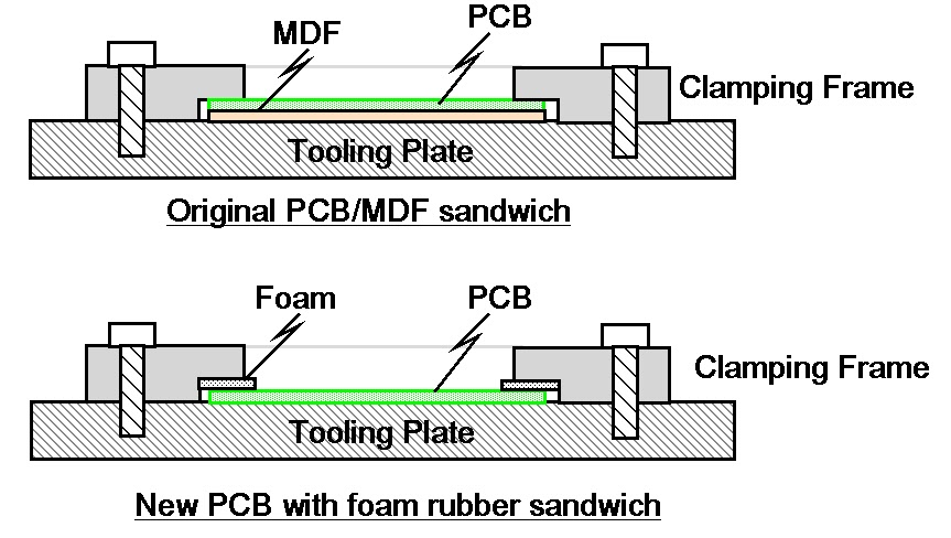
Any variation of the level of the PCB top surface will produce variable width cuts when using a V shaped cutter. I had machined a clamping plate which was a simple open frame with a clamping step equal to the PCB thickness (1.6mm) and a sheet of MDF or hardboard as a sacrificial backing board.
Despite having more clamping screw holes than a magazine burst from an AK47 I still ended with the corners of the PCB being a few thou lower. Results were shall we say ‘variable’. I had reason to run a new prototype board this week and once again hit the same frustration. In the end it was a sit and look at it and have a think session.
The resulting revelation was maybe the sharp edges on the step are applying too much pressure ? What if I were to be more gentle with the clamping ?
I cut some strips of thin foam rubber and put this into the step such as to push down on the PCB. As a quick test I only fastened the frame down using the four corner holes.
Sketches showing the two methods of clamping the printed circuit board ready for CNC milling
Absolute magic. The PCB surface hardly moved the Hamer needle at any point on the surface. Milling result was an artwork to be proud of.
Issues – the current step on the clamping frame is meant to clamp to a hard stop based on the sum of the PCB thickness and the sacrificial material thickness. Adding the foam meant I had to do away with the sacrificial board. The frame step therefore needs to be deeper. The sacrificial material is essential to allow drilling to take place without breaking the drill as it runs into and potentially damages the tooling table. (For the board in question I drilled to only 1mm and then over drilled by hand off line to the mill).
So a worthwhile bit of experimenting and hopefully a better result going forward
You will also have read about my preoccupation with trying to hold the PCB material flat to avoid variations in milling depth.
I have got it to a reasonably repeatable process using mechanical clamping but you know when a perfectionist starts something it has to be as good as possible …. step forward the Vacuum Clamping Table.
The thinking for this followed on from the Rosebud Grate experiments on my live steam locomotive. The grate consisted of a matrix of larger holes on the underside of the grate leading to a small bore hole on the top side of the grate. The theory as I understand it was that the reduction in size creates a Venturi type effect and boosts the air stream into the fire. I wondered therefore if I reversed the air flow i.e. sucked the air from the large hole into the small hole whether this would be beneficial in providing a boost of the suction. It is a bit tenuous I must admit and I can’t point to lots of science to back this up, but certainly worth a play.
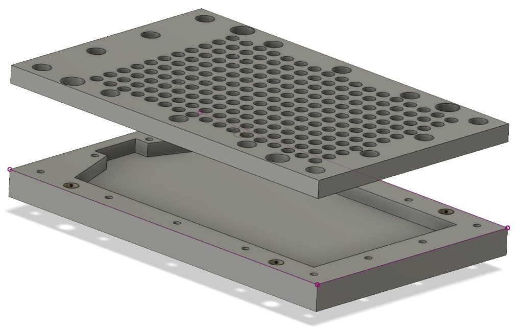
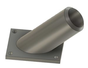
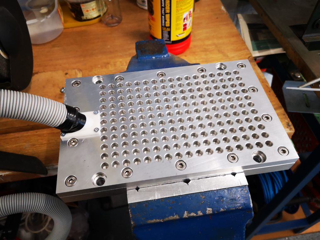
First stop was Fusion 360 and a two part plate was designed. This consisted of a top and bottom part. The bottom part is 15mm cast aluminium with a milled trough and the top plate is 10mm cast aluminium with 6.8mm holes (no science – this is tapping size for M8 that was already in a Tormach collet) on the top side that reduce down to 1.3mm holes (ditto also already in a collet) as breakthrough holes on the bottom surface. Around the edges are M6 screw holes to clamp the two plates together and also M8 mounting holes to fasten the plate to the tooling plate on the Tormach. I didn’t quite think the suction connection fully. After I had worked out the total area of the 1.3mm holes I realised that to accommodate this I needed a 16mm diameter hole for the air inlet. This was not going to be possible to mount on the 25mm overall edge of the plate. The solution was to 3D print a connecting pipe and mount this on the top surface. This adapts to the vacuum cleaner pipe being used as the suction source. The 3D printed adapter did not provide a good seal to the top plate so I had to fit a rubber gasket on it. The parts were all put together as shown below.
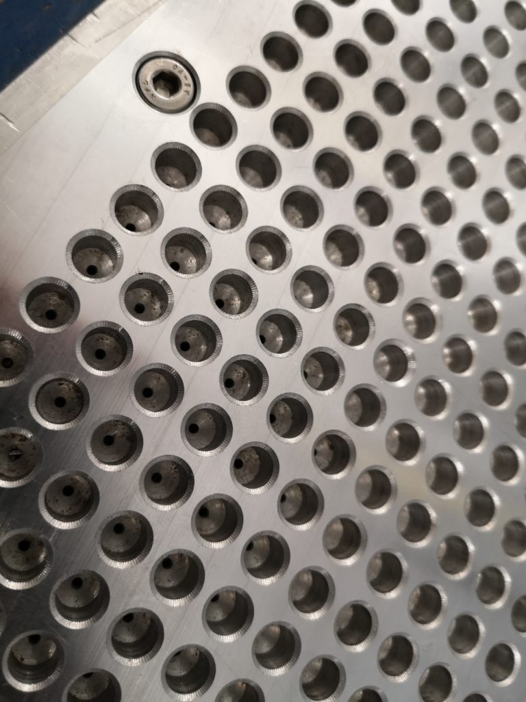
Finished vacuum plate on test in the bench viceClose up view of the 6.8mm blind holes leading to 1.3mm through holes
To my amazement it seems to work !
There does not seem to be leakage on the joint between the two plates and the vacuum pipe adapter with the rubber gasket seems to seal alright. If I put a large piece of PCB material over all the holes it is very difficult to move it. Single sided board is naturally bowed in the manufacturing lamination process and I can see it visibly jump flat when I turn on the vacuum. If the PCB is smaller than the total area of suction holes it does not seem to matter about covering over the ‘non-used’ holes to maintain the grip.
Proof will be when I try to run a board.
The milling process will not have major sideways pressure as the depth of milling is quite small so it should be fine. Clearly I can’t go drilling the component mounting holes in the PCB material with this holding technique but I can spot drill them to say 1mm depth and then finish them by hand having got a guide hole to start me off.
But all this will have to wait as the X axis limit switch has come apart on the Tormach and a spare has been ordered and is on its way.