I have been avidly watching Clough42 on YouTube. James comes over as a really nice guy and his presentation of his projects is excellent.
My principle interest is the Electronic Leadscrew modification to lathes. When installed this removes all the hassle of gearboxes and look up tables to be able to cut both Imperial and Metric screw threads and to set X axis movement feed rates.
The concept is simple but his implementation is second to none. A rotary encoder is fitted to the spindle to count revolutions of the chuck and a stepper motor (or servo hybrid) controls the rotation of the leadscrew. The resulting feed speed is derived from look up tables. The whole installation is controlled by a Texas Instruments LaunchPad C2000 microcontroller development board.
I have documented how I implemented this on my Myford Super 7 Big Bore lathe and the pdf can be downloaded below. There is also a ZIP file of all the Fusion related models for either CNC or 3D printing.
We are sitting in quarantine and now on Day 5. Not really any different to how we were before we went to France and when we were in France – just different jobs around the house and workshop and zero outside contact other than food deliveries. (My wife gets very excited at the prospect of seeing the deliveries arrive).
I got fed up with the boot warnings on Fusion 360 that Win7 would not be supported so I decided that I would upgrade to Win10. My machine is fairly well spec’d so there was no great desire to upgrade to a new machine. It was i7 based and had 32MB of memory with a 250GB SSD and a 1TB secondary drive. Both drives were pretty full and into red warnings so I bit the bullet and opted for a clean load. I bought in a new 500GB for the operating system and app storage and a massive 2TB data storage secondary drive. Total cost under GBP100 which is staggeringly cheap.
Changing the hardware was simple. I bought in a SATA to USB dongle to allow the old drives to be available for data transfer and this made life a bit easier.
Loading Win10 and all my favourite apps took over a day. It is just never simple. Finding software keys is always a bit of a problem as some apps hide it away in Registry. Finding EXE loading files is another frustration. Why when you buy an app do some providers send you an email link to download direct with a licence key ? This results in nothing showing in ‘Downloads’ history to refer back to and reload the app. When you try to use the old email link it downloads the latest version and tells you that your licence key is no longer valid. When you go to their site the version that did everything you ever wanted has been upgraded and needs you to pay to now use the later version. ‘Hello .. I have paid for version X and I don’t want to pay for version Y thank you very much. Just give me a download link to restore what I know and love”. Rant over on that one.
Some weird effects on Outlook transpired. I have a GMail IMAP account and three POP accounts all loaded on Outlook. After loading I had an extra ‘Sent’ folder on the GMail folders tree which contained the Sent items from one of the POP accounts. Spent a lot of time on this and didn’t satisfactorily solve it other than deleting the contents from this duplicate folder. The messages are still there in the POP folder so not sure what that was all about.
My 3DConnexion Spacemouse loaded across fine onto Win10 but I still had a related exception error window coming up on booting the machine. This was the same as it had been on Win 7 so clearly something was common mode. I could click it and the message window would disappear but it was annoying. After some digging I traced it to Trend Antivirus. If I put the two 3dconnexions’ Windows folders into Trend as ‘Ignore’ items it all went away. Progress on that one.
So I think I now have a (mostly) stable Win 10 machine. I hate all the nanny state Windows ‘fluff’ that stops you getting quickly to things such as System\Hardware like it was in XP. In an attempt to ease this I have loaded Stardock’s ‘Start 10’ which mimics the old style Start menu and this makes me feel a bit more familiar.
Hopefully this was all worth doing and things will now go swimmingly along with no crashes and dramatic improvements in productivity …. gosh were those really pigs I saw flying past ?
To date I have used Fusion 360 with just a mouse for screen manipulation. Over the past few months I seem to have developed Carpal Tunnel Syndrome in my right hand. (But there again it could just be old age taking its toll). This is painful at times but does depend on what activity I am undertaking. Some days just using a screwdriver can be taxing. I have begun wearing an elasticated wrist and thumb support which seems to have helped.
While watching one of my many favourite Youtubers mention was made of the big improvement in 3D image manipulation that can be achieved with a 3D mouse. There is also some evidence that such a device does ease the strain on the wrist.
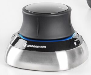
It seems there is one major player in the market and that is 3DConnexion. I went through my previously published decision making process on a potential purchase and my Wireless Spacemouse arrived yesterday.
It is supplied with a soft storage pouch and there is a training course app with it which is straightforward. You can then play a quiz to see how good your hand / eye coordination is. Perhaps it is not good to dwell on the results of this ….
Initially it is certainly weird to use but then it seems to click (?) with brain and muscle memory and then becomes a major step forward when using Fusion 360. You use your left hand on the Spacemouse and the right hand for normal mouse activity.
I like it. In fact I like it a lot and wonder why I hadn’t latched onto it before now.
Hopefully it will ease the strain on my right wrist and probably pass the burden to my left wrist …. arthritis rules.
Similar or related subjects : –
My TIG welding frustration suffered more than usual the other day .
I have an ESAB Warrior Tech helmet which works really well when welding but it would not stay flipped up when I wanted to see things in daylight. Every time I leaned forward the helmet would drop down over my eyes and thump me on the chest. Added to the fact I was trying to TIG some thin wall tubing I was no in no mood for distractions.
Before the helmet joined the happy hunting ground over the neighbours fence I took it apart to see why the latch up action was not working. Inspection revealed that the backing plate had cracked around the latching cam.
I could have bought a completely new head band assembly but the part in question might just be 3D printable. The Fusion 360 sketch ended up being very complicated based on eyeball guesses on curves and centres but on the second version I had a printed replacement which did the job …. for the time being anyway.
The final version of the replacement plate for the ESAB Warrior Tech welding helmet latch.
If anyone is suffering from a bruised chest let me know and I will forward the Fusion file.
You know how I keep on going on about how solutions to problems are often solved by coming at them from different and often unconventional directions, by utilising and marrying available resources ? It was a philosophy that I encouraged in my team while running my business and it has carried over into my way of working in retirement. A recent job brought his home to me.
A client had a very old clock that had had a new barrel wheel made and fitted but the clock would not run for more than a few minutes. There appeared to be an incompatibility either between the modulus of the new wheel and its mating pinion or the shape of the original pinion did not match the shape of the new wheel.
If you spun the barrel wheel you could feel the resistance build up as the synchronisation between the two profiles drifted out. Adding extra weight to the barrel helped but did not solve the problem.
So what to do ?
The barrel wheel was serious engineering and I did not fancy making a new one. The existing mating pinion was a seven leaf format and its leaves were what you might call pear drop shaped rather than the expected profile. The pinion arbor had a 72 tooth wheel driving the next part of the clock train but we did have a spare one of these to hand from the minute dial.
Calculations from the geometry of the barrel wheel resulted in a modulus figure of 1.86. A rather large value and not one that conventional cutters are readily available for. The pinion was perhaps something that could be drawn in Fusion 360 and then made on my Tormach CNC PCNC440 milling machine. The only snag was that the profile needed on the pinion would likely be weird and the world’s supply of brass could diminish rapidly while getting the profile correct.
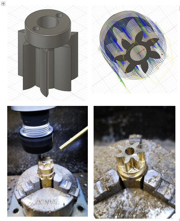
Using Gearwheel Designer I created what would be the expected profile for a 7 leaf pinion with a modulus of 1.86. This was exported as a DXF line drawing into Fusion 360. This outline was extruded in Fusion into a 3D design and a boss was added to mount the 72 tooth wheel.
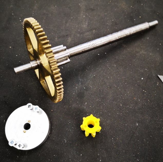
The design was 3D printed on my Sindoh 3DWOX printer and was mounted on a 6mm silver steel arbor. I added a driving disc that interlocked with the printed pinion and the crossings on the wheel to drive the assembly. Surprise surprise it didn’t run but it did mirror the regular pattern of stiffness of the original pinion.
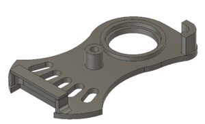
The original arbor, pinion and wheel together with the driving disc and a 3D printed pinion test profile. The driving disc has screws to lock it to the wheel and two protruding pins to lock into the 3D printed pinion profile under test. The 3D printed profile was a tight pressure fit onto the new 6mm arbor.
I now had the test bed for quickly making and testing different pinion profiles. There followed a number of hours watching the engagement progression of the profile of the pinion into the barrel wheel and then trying to conceive a profile for the pinion that might run.
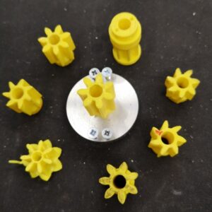
Various trial profiles and the temporary driving disc to engage with the 72 tooth wheel
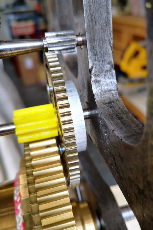
A test pinion in place showing the 72 tooth wheel and the driving disc
Fusion 360 made this process so easy and round 10 printed test profiles later I had success with a clock that now ran. The driving weight on the barrel was around 11kg and it looked to be worthwhile wasting some brass making a ‘proper’ one.
I took the 3D design and produced CAM code in Fusion. This would cut the profile ‘on end’ using an adaptive first cut with a 4mm end mill followed by rest machining the remaining material with a 2mm end mill.
The Fusion 3D model of the pinion, the CAM simulation of the leaf cutting, first adaptive cut of the leaves and rest machining final pinion
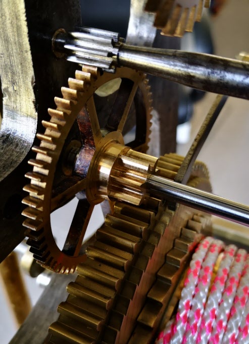
The resulting brass pinion was mounted on the arbor and the clock ran with a strong beat. As expected the brass pinion gave less surface to surface resistance than the 3D printed part and the barrel driving weight was now able to be reduced down to 6.25kg.
The finished pinion mounted in the clock on the new arbor
I ran my Microset Timer on the clock overnight and had a first off timing error of 5 minutes per day which was fixable with a pendulum tweak. The movement had an instability of a few seconds per day which was quite astonishing.
The conclusion of the experience is that at first glance this seemed like a conventional pinion cutting exercise …. but M1.86 cutters are not readily available. If a cutter could have been found at less than a King’s Ransom it is likely that the resulting conventional profile would have been wrong to match the barrel wheel.
The alternative route that was taken of Gearwheel Designer to Fusion to 3D print to Fusion CAM to CNC machining solved the problem albeit with a final weird profile. The purists and traditionalists will groan. There will be a gnashing of teeth and a pulling out of hair.
Does it really matter if the result is new life for what could have become a heap of scrap metal ?


 It is supplied with a soft storage pouch and there is a training course app with it which is straightforward. You can then play a quiz to see how good your hand / eye coordination is. Perhaps it is not good to dwell on the results of this ….
Initially it is certainly weird to use but then it seems to click (?) with brain and muscle memory and then becomes a major step forward when using Fusion 360. You use your left hand on the Spacemouse and the right hand for normal mouse activity.
I like it. In fact I like it a lot and wonder why I hadn’t latched onto it before now.
Hopefully it will ease the strain on my right wrist and probably pass the burden to my left wrist …. arthritis rules.
Similar or related subjects : –
It is supplied with a soft storage pouch and there is a training course app with it which is straightforward. You can then play a quiz to see how good your hand / eye coordination is. Perhaps it is not good to dwell on the results of this ….
Initially it is certainly weird to use but then it seems to click (?) with brain and muscle memory and then becomes a major step forward when using Fusion 360. You use your left hand on the Spacemouse and the right hand for normal mouse activity.
I like it. In fact I like it a lot and wonder why I hadn’t latched onto it before now.
Hopefully it will ease the strain on my right wrist and probably pass the burden to my left wrist …. arthritis rules.
Similar or related subjects : –