Introduction
This write up is not for the purists with years of experience but is an explanation of how I thought through how to machine something over size that would not fit into my Tormach PCNC440 milling footprint as a single operation. Hopefully it might help others to grasp the process.
The challenge began when a local turret clock expert came to me and asked if I could machine a new Hour and Minute Hand for a clock he was working on. The Hour Hand was around 14” long and the Minute Hand some 18” long.
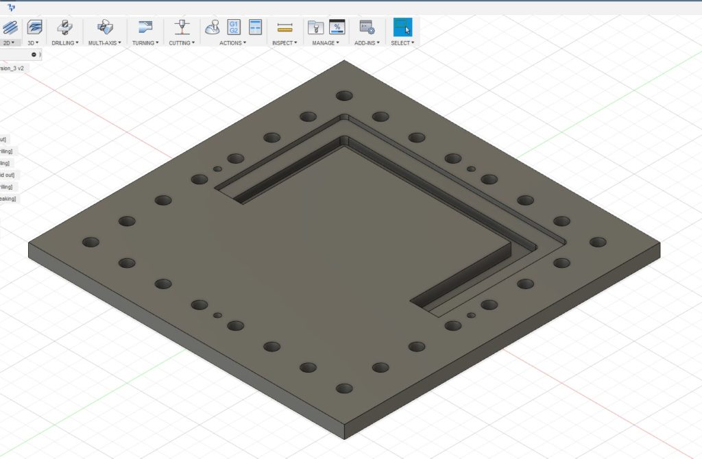
Here is the Fusion 360 view of the minute Hand.
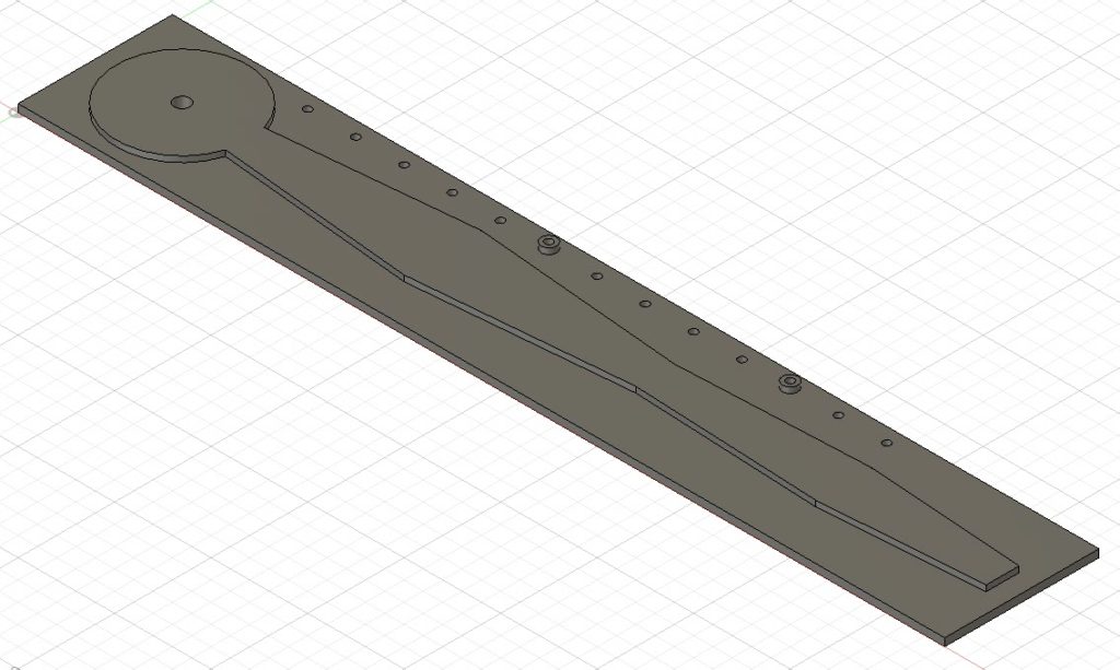
Clearly these lengths were way outside the 440 table X movement (10”) so a plan was needed. There then followed a lot of staring into the distance at mealtimes and also at bedtime accompanied by vocal “hmmm”s as I tried to mentally visualise what was needed. This idiosyncrasy is something my wife has come to terms with over the years…..
My conclusion from this mental preparation was that I needed to be able to accurately step the stock across the tooling table and then take two or three bites at the profile machining.
What follows would almost certainly benefit from a video but sadly I am not set up for this.
Click the link below to download the PDF document.
Similar or related subjects : –
- Parting Off on the Lathe
- Workshop storage update using Spacemaster 5L boxes
- Plastic heat sealer – a useful workshop asset
- How to square up a scrap piece of stock ready for machining
- Deburring techniques in the home workshop
- First screw threads cut using Clough42 electronic leadscrew
- Machining a job that is outside a milling machine’s table travel using Fusion 360
- Stevenson Collet Block and the Angle of Dangle
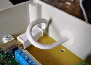
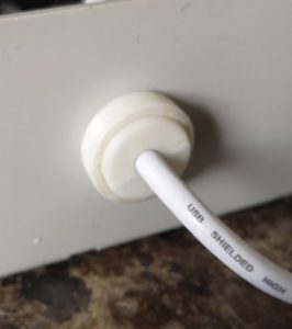
- A Lazy Cable Clamp using 3D Printing
- Mill Turning Jig
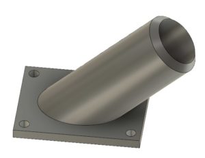
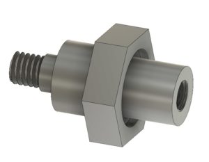 It is made from a piece of 19mm AF hexagonal steel bar with the hexagonal flats going to be used as a tightening it in place in the Tormach arbor. My Myford Super 7 when used with a 3 jaw self centering chuck is not bad on concentricity but for really accurate centering I swap the chuck for a collet face plate instead. This job was going to need both.
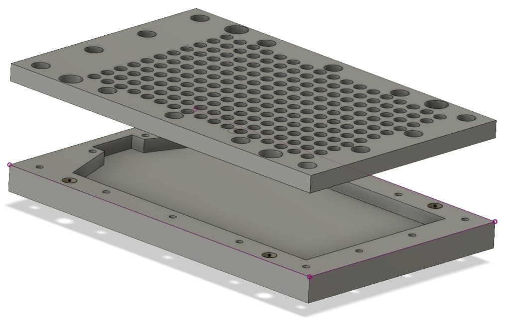
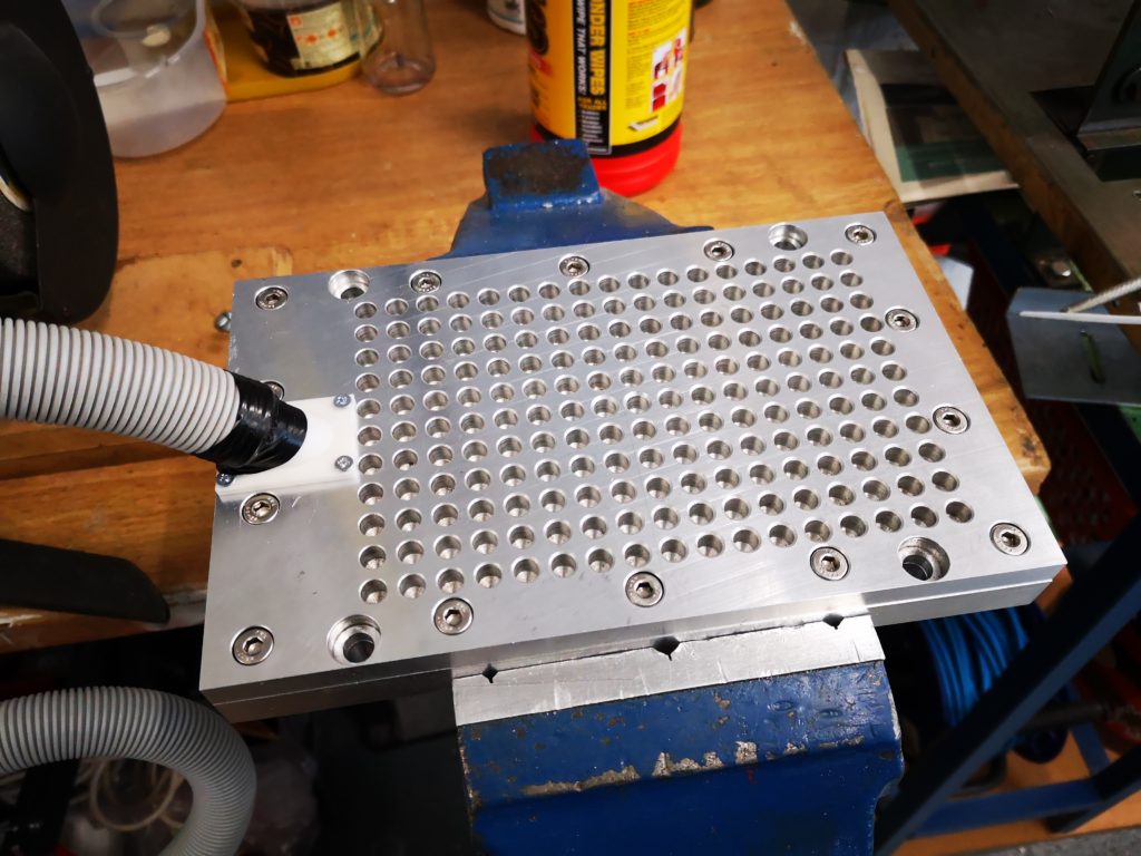
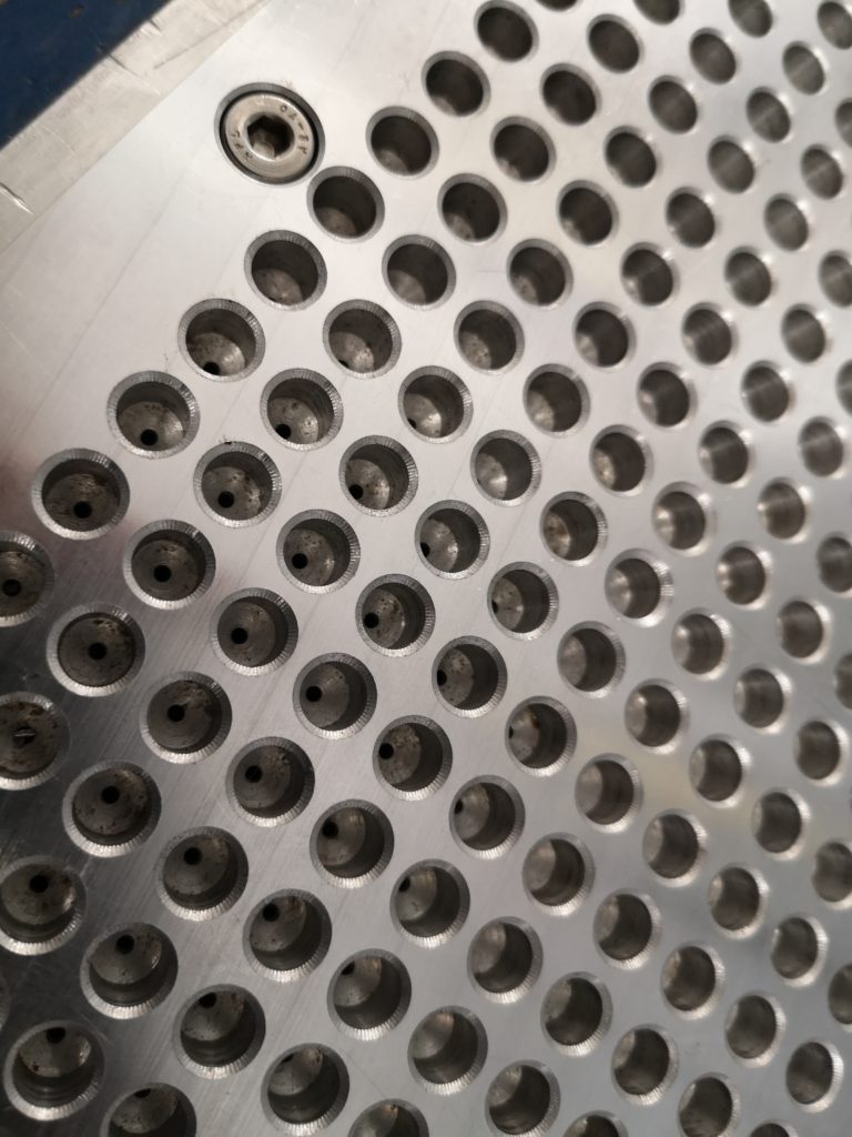
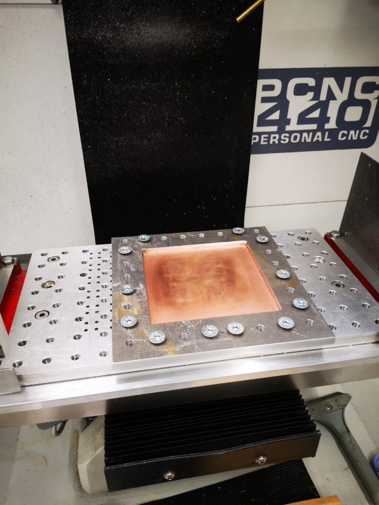
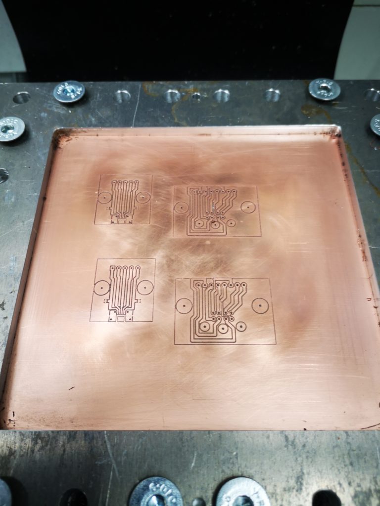
 The outer holes are for the M8 clamping to the table and the four smaller holes are the tooling holes. Being tight with my materials I did not want to just mill out the centre of the plate and have a mountain of swarf (chips). Instead I designed it with two slots as shown, one for the clamping surface and one that almost cut through the stock. The partial cut was to ensure the central piece did not flip out once cut free and damage my cutter. First one half was drilled and cut and then the plate was rotated 180 degrees and the second half cut. This left the central island just held in place by less than 0.5mm of material. This was easy to hand cut through to liberate the central area. The plate was then turned over and the cut edge cleaned using the same tooling position and doing the same 180 degree rotation. To my surprise the rotation process on the tooling pins worked very well with only a minor step transition at the overlap point on all cuts. This was probably more down to my 3.7mm tooling pins being not quite concentrically turned from 4mm silver steel. With this finished I now had a much more robust clamp for the PCB material. I had made the clamping step 4mm deep so I could put sacrificial backing boards behind the PCB being run. This would allow drilling through as needed. Checking the flatness of a clamped PCB blank with my Haimer showed variation of a few thou in the top surface of the PCB Z position. The worst case variation in Z was at dead centre where the PCB’s natural bow was most dominant.