

I am indebted to Chris at Clickspring for sowing the seeds to so many ideas and projects. This is a straightforward ‘one day-er’ to make eccentric clamping nuts for a milling tooling plate. I designed it around M8 fastenings but the idea can be scaled to suit.
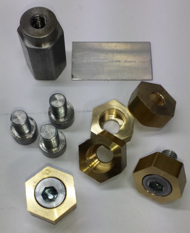
The image below shows the finished items and the screw adapter jig and the scrap piece of 1mm plate that is used to create an offset in the machining process.
Material Needed : –
M8 cap head screws (these can be full head or reduced height versions). I buy 30mm length screws for bulk stock and then cut them down on the lathe depending on the application.
An approximate 35mm length of 20mm AF hex mild steel bar (but you could also use a length of the brass bar as listed below).
A length of 20mm AF hex brass bar (length depends on how many nuts you are making).
A length of 12mm or 1/2″ OD steel tubing with a 10mm ID.
A piece of 1mm thick material of any type as an offset plate.
Solder paste.
Dimensions

Process
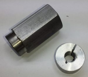
Face off the end of the hex steel bar and tap to M8 to a depth of 15mm or so (not critical and depends on the length of the screws you have available). Note that I reduced a short length of the end of the bar so I could more easily access shorter screws when they had wound fully into the end of the bar. This bar will now be the screw offset jig.
Slacken off the chuck and with the offset jig in place and then put the piece of 1mm material under one of the jaws and re-tighten. This makes the hex bar jig run eccentrically in the chuck.
Screw the first of the cap head screws into the end of the jig and turn down the head to be a sliding fit into the end of the steel tubing. Remember the jig and the screw are running eccentrically so move the cutting tool very gently towards the revolving screw head. Once the diameter of the screw head matches the ID of your tube stop the cutting but leave the jig and screw in place in the chuck.
Cut a length of the tubing to match the overall screw head height/length plus a couple of millimetres. Coat the inside of the tube and the outside of the screw head with solder paste and slide the tube onto the eccentric screw head. Position the tube so it is centrally positioned on the screw head to give you a small amount to machine back square.
Heat the tube and the screw head with a blow torch to re-flow the solder paste. (You could use Loctite instead if you prefer).
When cooled, face off the combined screw head and tube assembly.
Take a fine cut off the outside diameter of the new head outer surface to ensure it is running true to the jig offset.
Remove the offset jig from the chuck and remove the screw.
Using a split nut collet, grip the M8 screw in the lathe. The screw thread will now be running true in the lathe but not the head. Face off the rear of the combined tube and screw head assembly and also undercut the threads close up to the new screw head for 2mm to leave a core depth of 6mm.
For my version the overall screw thread length needed to be 9.5mm plus the tooling plate depth so I had to cut my 30mm stock screws down to length. I used the split collet to face off and tidy up the cut end. This completes the screw modifications and the new head will be around 7mm tall.
Chuck the hex brass bar and face off.
Centre drill 8mm diameter and to a depth greater than 10mm.
Counterbore the hole to a depth of 7.5mm and to a diameter that snugly matches your newly created eccentric screw heads.
Part off the hex brass bar at 9.5mm. Nut head completed.
Conclusion
The eccentric screw drops into the brass nut and once mounted on the tooling table will eccentrically rotate to grip an object on the table. This is particularly useful when facing off a block of material and you do not want tooling clamps protruding above the top surface.
Practically you fit the nuts onto the table at appropriate points around one side of the workpiece with the eccentric screws turned to be at their minimum rotation. Clamp the other side of the workpiece with conventional sliding clamps that are pushing the workpiece firmly against the nuts. Now rotate the eccentric clamping screws to push the nuts tightly against the workpiece.
Once in the swing of the process of making these nuts you get into a routine. For instance I cut all the required number of tube sections to length to start with, then machined all the screws and then all the nuts.
Note I only had some seam welded tubing in stock. This had a horrible ridge in the internal surface so I had to drill out with a 10mm drill bit to clear this. It wasn’t perfect and it resulted in my having to skim more off the new nut head OD to make it run true. It was important to make the screws first so I knew if I had to adjust the internal counter bore on some of the brass nuts.
The concept described can be adapted to any size clamping nut dimensions and any variant of the style of clamp.
Thanks again Chris for sowing the idea !
Warning – Clearly this method of clamping is not as strong as a downward clamp to the table so care has to be taken in not overloading these clamps by taking too deep a cut with the mill cutter. That aside they are really useful for low profile clamping.