

Updated Laser Centring Tool for use with the Tormach TTS Collet
NOTE – THERE IS AN EYESIGHT HAZARD ASSOCIATED WITH THE USE OF LASER DIODES AND THE AUTHOR DOES NOT ACCEPT ANY RESPONSIBILITY FOR ANY HARM OR DAMAGE CAUSED TO AN INDIVIDUAL OR INDIVIDUALS THROUGH THE MISUSE, ACCIDENTAL OR OTHERWISE OF SUCH DEVICES.
Elsewhere in my pages there are details of a laser centring ring that I made for my Myford manual milling machine. It consisted of a ring of Acetal with a laser diode and two button cells activated by a microswitch when the ring was pushed onto the mill spindle. The design was published in the UK magazine Model Engineering Workshop #253.
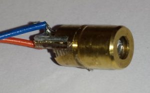
The project was based around a 6mm diameter 3V laser diode available on Ebay. The front section of the body contains a lens to focus the diode beam.
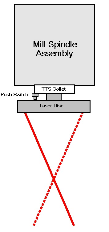
The concept is for a simple but useful addition to aid milling set ups. Unlike conventional laser pointers this is not just a beam down the centre of the Z axis but an offset beam at an angle of 10 degrees that creates a ‘cone’ of light when revolving on the mill spindle. The cone can be enlarged from a single dot up to a large circle by increasing or decreasing the Z height above the work piece.
Why bother you might ask ?
For a quick and dirty set up this is a wonderfully simple addition to the mill that allows centring on any position on an existing job or a new item layout. By moving the Z axis up and down the cone of light will diminish from a circle of light down to a dot and the expand out once again to a circle. This allows centring on existing holes by making the circle symmetrically ‘fit’ around the hole. If you have a piece of material in the vice and you need the centre line the circle can be expanded to just touch the vice jaw edges and you now have the centre of the material. It is also useful when using Stevenson Collet blocks to find their centre line for cross drilling rods.
OK I agree you could use your Haimer or other edge finders with DRO but sometimes you just want something quick and “near enough”.
By now you are all aware that the Tormach PCNC440 has arrived in my workshop (joy of joys) and I missed not being able to use the old Myford dedicated centring ring on the Tormach. The problem was that the Tormach spindle did not protrude in the same way as the Myford so how was I to fix it in place ?
I have the Tormach Tooling System (TTS) and the Power Drawbar options on my 440 and this got me thinking ….
The TTS has a standard set of collets and chucks that all have a 19mm (0.75″) diameter shaft that is clamped into a mother collet held permanently in the Tormach spindle. The power drawbar uses compressed air to push down on the collet and open its jaws to receive the required tool TTS shaft. The power drawbar is a wonderful addition to the Tormach Mills.
If I could create an assembly with a 19mm (0.75″) shaft this could be locked into the TTS mother collet like normal tooling and the problem solved.
No more Acetal swarf (chips) …. over to Fusion 360 ….
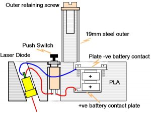
I designed a ring containing the diode and batteries (2 x LR44) with a spindle collet mounting shaft protruding out from it. The diode was mounted with a 10 degree angle offset. I could have designed and printed the 19mm collet shaft totally in PLA but I figured it would not last long being clenched in the power drawbar mother collet. Instead I made it undersize and fashioned a 19mm steel sleeve slightly longer than the PLA to slide over it to protect it. A bolt and washer than clamp the sleeve down onto the disc. Had I just modelled the shaft in PLA it would have slowly ground away and contaminated the mother collet action.
So I now have the ring and the means of fixing the ring into the collet. In order to save battery life and to protect eyes from accidentally being caught by the beam I needed some means of automatically turning the laser on.
Looking at the physics of the spindle end I decided I could activate the laser with a small push button protruding from the top surface of my ring that would get pressed by the action of the power drawbar dragging the disc shaft up into the mother collet in the spindle.
Graphically and electrically it looks like this : –
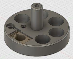
The design was now in place and ready to print on the Sindoh 3DWOX. Now I don’t know about you but I am pretty tight in not wasting PLA if I don’t need to so I put some holes in my ring to cut down the printing waste. I know this would imbalance the rotation of the ring but it would only be used at slow speeds.
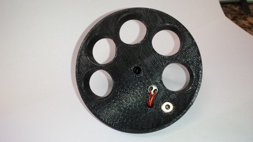
I also designed in various grooves to run the wiring in so I could back fill with black epoxy once the ring was completed. In particular there needed to be a through hole to bring the wiring from the push switch from the lower side.
The assembly took just over 3 hours to print in the Sindoh using standard resolution.
Here is how the design looked in Fusion 360 :-
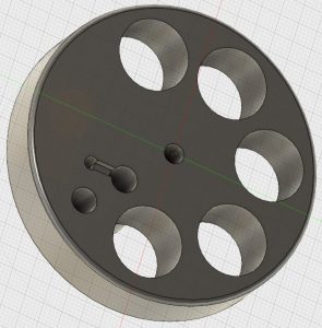
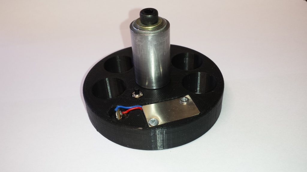
Below is the finished disc. You can see the steel sleeve on the PLA shaft held in place with a M5 cap head. On the disc top surface you can see the small push button, the connections to the laser diode and the battery cover plate.
For more details refer to the earlier version for the Myford.
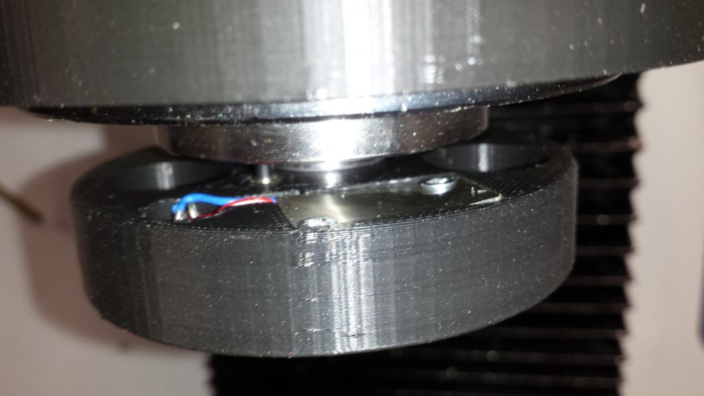
The shot below shows the disc in place in the Tormach spindle TTS mother collet. You can just see the push button impinging on the Tormach spindle.
Set Up Notes
First of all the laser diodes as delivered have their focus set for long distance operation. For this application you need to twist the lens on the front of the diode to re-focus on more close up objects. This is best done before mounting in place in the disc body. Set up a simple but solid test rig and tweak to focus.
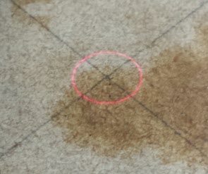
Secondly it is important to ensure that the laser when mounted is beaming dead centre through the Z axis centre line. For this reason the laser mounting hole needs to be a little over size to give some adjustment space. Some deft pushing and pulling is needed on the diode in its mounting hole to achieve this. (I soldered a small loop of wire on the positive terminal of the diode to give me something I could easily grab with tweezers). Without making this adjustment the laser beam will never converge to a single dot but instead will only reduce at best to a small circle. The easiest way to achieve this centring is to put a piece of cardboard or paper on the mill table with a cross hair drawn on it. Run up the mill with a fine drill or similar in the spindle to aid centring the spindle on the cross hair. Once centred, do not move the X or Y axis. Swap the drill collet for your new laser ring and then without running up the spindle, wiggle the laser body in the disc until the red laser dot is centred on the cross hairs. You will have to tweak the Z axis up and down to find the cross over point where the laser light ‘cones’ diminish to its minimum. Once you are happy it is correctly positioned, run the spindle up to check the central position and move the Z axis up and down to verify operation. When all is well bond the diode in place.
Closing Comments
While I have made the laser ring specifically for my 440, it can be used on any of the Tormach milling machines using the Tormach Tooling System with a 19mm (0.75″) shaft. By changing the steel protective sleeve dimensions it could have a wider appeal.
No originality is claimed for the concept but I offer the idea for the implementation specific to the Tormach TTS. I can send interested parties the Fusion SLA file and a parts list if of interest. Either send a comment request or use the email address on my About page.
Can once again I must emphatically repeat ..
THERE IS AN EYESIGHT HAZARD ASSOCIATED WITH THE USE OF LASER DIODES AND THE AUTHOR DOES NOT ACCEPT ANY RESPONSIBILITY FOR ANY HARM OR DAMAGE CAUSED TO AN INDIVIDUAL OR INDIVIDUALS THROUGH THE MISUSE, ACCIDENTAL OR OTHERWISE OF SUCH DEVICES.