

With hindsight building the William Smith Gravity Arm Gearless Clock was ambitious for a first time clock project. There are nearly 100 pieces that need making and then there is the time needed to get an understanding of how it works and then set it up.
That having been said, the project represented a wide ranging learning experience of making a clock and the techniques involved.
Bill’s book begins with a discussion of the background and an explanation of how the clock works. For me it was not until I had built it and was struggling to make it work that this early part began to make sense.
There then follows a detailed listing of the tools you will need and their uses. It is a good shopping list and contains a common listing of items needed for all clock related activity.
The book than moves into the making of the clock. To help me gain a better feel for the items needed I created a spreadsheet showing materials needed and status. Follow this link to see my sheet Bill Smith Project Parts Lists.
The early work is not too taxing and there is always a different way to do things to suit what you have to hand. For instance I made the pendulum bob ends by sandwiching two sheets of brass together rather than machining from solid.
My most memorable learning came next on the Bill’s so called SuperGlue Arbor. Something that I now use regularly not just in the lathe but also on the milling machine.
Another simple trick is to the lining of the bob case with cartridge paper when casting the lead inner.
I tried to be clever with the solenoid coils and buy ready made ones off Ebay. I could not get something that worked and I needed high current from the battery. In the end I reverted to winding them as per Bill’s instructions. I did use printed circuit board discs as the winding end plates instead of phenolic sheet.
When it came to cross drilling the various posts I used a Stephenson Collet Block rather than V Block. These are lovely items to have and are available with square and also hexagonal bodies and in various collet set sizes.
Winding springs was a new learning curve and is now something I do regularly.
I purchased a Mumford Microset for timing adjustment and would not be without it. You do need the computer interface to really see what is going on.
Which brought me to the wheel cutting section. Once again I followed Bill’s advice and obtained the Sherline CNC rotary table and made an adapter to fit into the rear of the Myford headstock bore. I could not have done the pin wheel without this.
There are odd mistakes in the text, the most serious is an apparent error in Fig 11 on page 97 which caught me out and lead to a new timing plate being needed. The error goes back to the plate dimensions as shown on page 77 and should read 6 3/8″ wide not 5 5/16″.
The Dodd Daisy is a pain to make and cries out for CNC but I did not have it so out with the files.
Some other edits I made : –
I increased the weight of the gravity arm weight to make it drop harder and kick the pendulum more. This meant reset times were longer.
I also changed the way the seconds wheel activates the minutes pawl. This involved replacing the ‘deep notch’ concept with a simple pin on the seconds wheel. This is difficult to describe so I will add some pictures to explain.
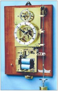
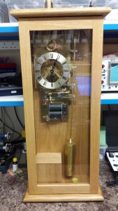
My brother in law made me a case to suit and the clock is now finished subject to some final polishing of the parts. Below is an overall shot of the clock and you can see the battery box in the bottom left.
I was impressed with your clock,and interested to know your wiring diagram to eliminate sparking across the contacts . Also what metal was used for the said contacts. I have made the Murday reason clock ,the coils are similar to yours and it I corporates the hill toggle , I used a 10 ohm resistor along with a rectifier diode across the coils ,and although it works fine to a point , does not eliminate sooting up of the contacts over time.
Hi Peter and thanks for your message.
Regarding the contacts I bought in a short piece of silver rod and made two buttons embedded in a brass former. These seemed to wear well.
Regarding the back emf problem, I just had a single diode (1N4001) across the coil and as close as possible to the coil terminals.
Since making the clock I have modified it to replace the hip toggle and gravity arm with an Arduino based pulsing system. This uses two Hall Effect sensors to indicate mid swing and overswing. I count the swings and after a defined number and a defined delay, I get the solenoid to kick a magnet on the pendulum rod. If the swing increases too much in amplitude the overswing Hall Effect keeps resetting the counter until it has dropped to a safe level. Why did I do this ? My wife would not have the clock in the house as it made so much noise with the gravity arm reset. It is now whisper quiet and there is promise of a piece of wall space for it in the house.
Woody
Hi Woody,
I’m considering building this clock, and your Hall sensor modification looks appealing. The Hipp toggle gives me reservations, along with the frequent gravity reset noise you mention.
Do you plan to post the details on your website?
Regards,
MG
Good afternoon and thanks for reading my blog.
The Gravity Arm clock is a ‘work in progress’ job in that I keep sneaking up on it when nothing else is on the go and tweak it some more.
The replacement for the gravity arm pulse mechanism is complete and works well. It is committed to a printed circuit board and easy to reproduce.
I can’t say the same for the motion work ….. It does work but it still drops the odd minute each day.
I know this occurs when the swing amplitude is at its lowest and the the pin wheel hook does not get a clean ‘pull.
If I increase the pulsing rep rate then this better maintains the swing amplitude but then the battery consumption increases which I am trying to minimise.
I really should have another focussed session with it but there is always something else distracting me.
You can be assured that if and when I crack it I will write it up.
If you want the Arduino controller board and code you are welcome to the design details and maybe with two of us looking at the motion work we might progress.
That aside the clock was nice to build and if you just make the motion work then even more simple. There is one mistake in the write up regarding the hole positions of the motion work mounting plate to be aware of.
Let me know if you want to progress this and email me on the address on the blog.
Kind regards
Woody