

This write up was originally submitted and appeared in Model Engineering Workshop magazine.
- Background
Like many home engineers I bought a laser centring tool at one of the engineering shows. This had a 10mm shaft and fitted into a mill collet. It produced a fine red light beam vertically downward onto the job when held in the collet. Provided you had the mill running it would give a somewhat circular indication of the mill axis centre but rarely a distinct fine dot. I tried aligning it for a better centre dot but it seemed to have a mind of its own. Consequently it was not getting used much.
I subsequently came upon Mike’s Workshop site
(http://mikesworkshop.weebly.com/).
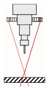
Mike showed an alternative idea for a centring tool whereby the laser diode was offset on an arm. This produced an hour glass shaped dual cone of light which converged to a dot at the centre position as the quill was moved up and down. It allowed centring to not just centre punch dots but also by widening the circle with up and down movements of the quill, you could accurately centre on flat and circular jobs. Mike gave reference to a You Tube site by Dan Gelbart which illustrated this potential (https://www.youtube.com/watch?v=otSjut1iGGk). A pictorial view is given below.
Mike’s design was made and it lead to a nasty bruise as the rotating arm attacked me when I got too close. It was also frustrating in that it still needed to be put into a collet for rotation and use. The device shown in Dan Gelbart’s video appeared to slip over the chuck and so did not need to be held like a tool in a collet. It also meant the device was much higher up the quill and less likely to add to my bruises. Dan Gelbart was enthusiastic about the device but did not indicate a source. A web search did not turn up anything so I resolved to produce something similar for my Myford VMB mill.
- Practical Implementation
A 25mm slice was cut from the end of a 100mm diameter rod of HDPE (Acetal or Delrin would be similar). This was chucked on the lathe using external jaws and both faces turned square. HDPE is not the best of material for machining as it soft and ‘soapy’. The slice I had cut did not run true so I marked jaw #1 position for reference. This meant I could take it in and out of the chuck and reposition after checking for fit on my VMB quill boss. On completion I had a ‘halo’ disc ready to mount the diode, battery and a switch ….. and a large pile of plastic swarf.
The 3V laser diode was sourced on EBay together with a small lever arm micro switch. The switch was to allow the laser to be switched ‘ON’ only when it was in place and gripped on the quill boss. This was thought to be a good eyesight protection mechanism and would also be a battery saver. I tend to forget to turn battery devices off … and this had a potential eyesight hazard if left lying around.
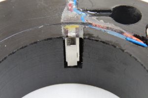
Mike on his site suggested a 75 degree angle for the diode mounting. This was duly drilled into the disc as close as possible to the edge. A partially milled slot was milled on the inside diameter face to take the micro switch. The connecting wires were soldered to it and then it was potted in place with twin pack. A 12mm blind hole was slot milled to take two LR44 button cells. The battery hole also had a small slot down its side to allow the battery wire to be passed out. Slots were milled on the top surface of the ring to allow the wiring to be potted into the disc.
The battery contacts consisted of two parts. The positive battery contact at the bottom of the hole was made from a 12mm disc of nickel silver (but could be any conducting material). I left a small tag off one side for the wiring connection which would pass up the slot in the sidewall. The negative battery contact at the top of the hole was a piece of printed circuit board. This was profiled to fit into a milled recess in the top surface of the ring and held with two M2 fastening screws to allow battery changes.
- Diode Power Source
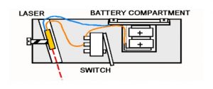
The negative connecting wire was soldered to the underside of the pcb surface. If the 12mm hole is drilled too deep then you can either build up the surface of the pcb with solder or solder a small spring in place to make up the shortfall. A pictorial view of the wiring arrangement is given below.
Some means of fastening the ring in place on the quill boss was needed and after experimenting with magnets and O rings, I defaulted back to making a simple 6mm Acetal screw with what I thought would be a nice HDPE knurled knob. Have you ever tried to knurl HDPE ….. ?
- Modification
In principle the job was complete but I should have done the physical mathematics first. While the disc fitted well and the micro switch mechanism worked etc the diameter of the disc was clearly defining the maximum distance of the diode from the central axis. With such a limited diameter disc the laser beam was blocked when the collet nut was in place. I also found that my diode mounting hole was not accurately aiming in line with mill quill central axis (try saying that after a few beers). This meant that when the quill was wound up and down over the job, the beam circle would never achieve a dot, it came close then expand out again. It was going to be difficult to adjust this with the design as it was.
Reluctant to start from scratch and make more plastic swarf, I decided to add a ‘power bulge’ off the side of the existing ring which would now contain the diode. This had two benefits. It increased the diode mounting distance from the axis and so avoided the interference of the collet nut with the beam. It also meant that the diode mounting could be finely tuned to adjust the beam direction to allow alignment with the quill axis. A grub screw was also fitted to grip the diode once aligned in its mounting hole. This additional mounting block was made from Acetal.
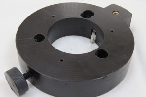
Here are various views of the finished item. Ignore the various unused holes which are from my first attempts.
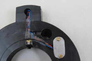
The assembly was re-wired and the wiring potted in the milled channels with twin pack.
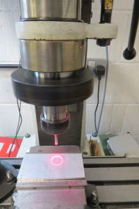
This power bulge modification to the ring fulfilled all the objectives and I now had a very useful alignment aid that could be quickly slipped on and off the mill quill boss. I can now align to a point on a job or find the centre of a work piece while leaving a tool in place in the collet. The following pictures show the device when fitted to the Myford VMB.
- Conclusion
I have not gone into detail on dimensions as clearly the design is dependent on the quill boss dimensions and available materials. No originality is claimed for the concept and this article has been written more to stimulate and popularise this simple idea.
With the arrival of the Tormach PCNC440 I am going to need a similar device …
NOTE – THERE IS AN EYESIGHT HAZARD ASSOCIATED WITH THE USE OF LASER DIODES AND THE AUTHOR DOES NOT ACCEPT ANY RESPONSIBILITY FOR ANY HARM OR DAMAGE CAUSED TO AN INDIVIDUAL OR INDIVIDUALS THROUGH THE MISUSE, ACCIDENTAL OR OTHERWISE OF SUCH DEVICES.