It is likely to make my Dremel redundant.
I came across the Fanttik via a sponsor link on a YouTube channel. I had just struggled with a fine engraving job where my Dremel was just too large and unwieldy for the delicate work involved. Out of curiosity (and frustration) I bought the Fanttik and was very impressed with the quality. The packaging of the product was on a par with Apple and product casing impressively over engineered.
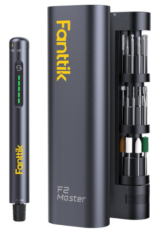
Maximum speed is 25,000 rpm and it is supplied with carrousel of tools. There are plenty of sources of spare 2.3mm shank tools available on Amazon including sets of drill bits. (The 2.3mm shank standard means that most Dremel tools are not suitable).
I recently made a modified version of the 3D printed JSK soldering iron brass insert press. The JSK design is well thought out, is rigid, spring loaded and works very well. (Note that I had to print the column in two sections as my Qidi X Smart build volume was too small). I made a revised gripping sleeve for the press to grip the Fanttik so the press now acts as a mini drill stand for small diameter holes such as on PCBs. The run out on a 0.8mm drill bit was not visible to the eye. Here’s the finished press. Excuse the perforated base plate – you have make use of what is functional and to hand.
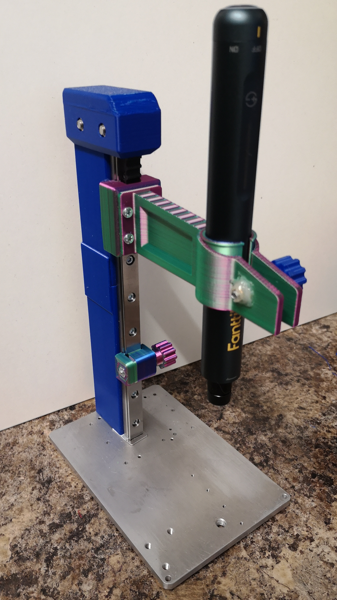
More workshop tooling …. but this one ticks two boxes, insert press and mini drill with a quick swap out depending on activity.
Links to similar or related post are listed below : –
- Fanttik super tool is well worth a look
- Small handheld vacuum cleaner
- Eccentric Engineering Turnado freehand turning tool
- Rotring 300 2mm clutch pencil modification
- Kindling Cracker – a safer option
- SINO SDS2MS DRO repair
- A useful Amazon sourced small item storage system
- 3D Printed Threads Modelled in Fusion 360
- Three axis stepper controller PCB in stock
- Myford Super 7 Large Bore depth stop