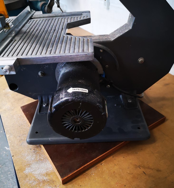
I had a contact through my blog from a gentleman who had inherited a Burgess Bandsaw. I have published various support details for the BK3 so he was curious about the model in his possession and he sent me some pictures as shown below.
I have never seen this model before. The BK1 through BK3 all have a belt drive from the motor but this one has a chain drive. The shape of the housing is much more curved and both the blade wheels look to be cast and perforated rather than being plastic. It is clearly a very early model, probably before the design went through a manufacturing cost reduction.
The manufacturers plate suggests this is Serial #225.
If anyone knows the likely history of this version I would be interested to know more details.
Links to similar or related post are listed below : –
There is no doubt that adding the Lazy Susan rotating base to my BK3 Burgess Bandsaw has been a good move. Being able to adjust the orientation of the BK3 to suit the material being cut makes life so much easier.
The one issue that has come to light is when adding heavy pressure to the cut I was having to push the material with one hand while trying to stop the BK3 rotating with the other hand/arm/knee.
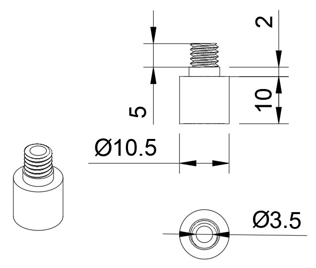
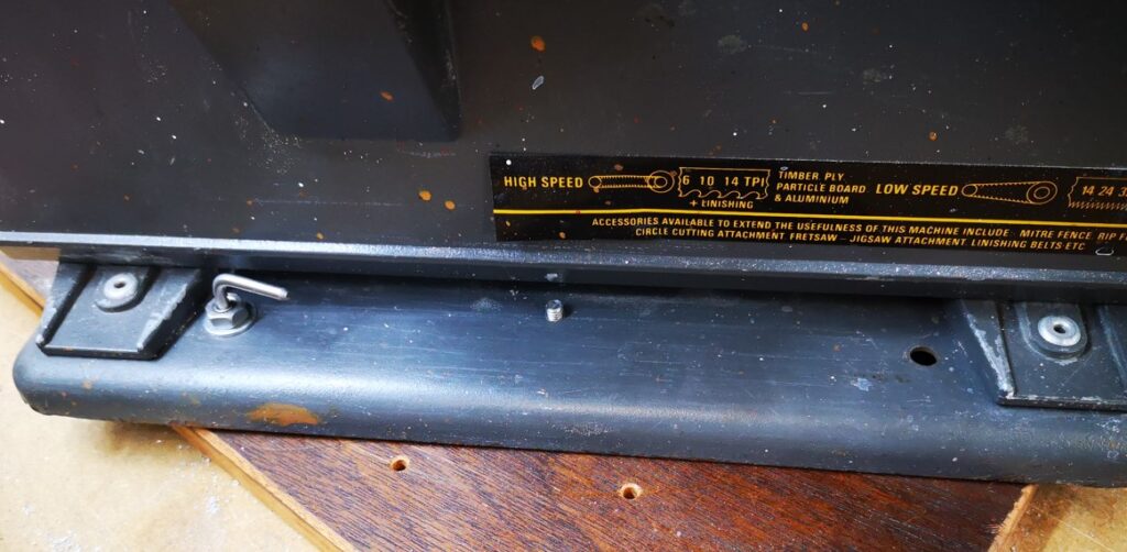
Following one such episode I have added a stop pin that locates into preset holes in the new wooden base. I used one of the four unused holes in the original BK3 baseplate as the pin locating point. These holes are 6.5mm diameter (probably 1/4″ originally). I could have used a 6.5mm rod pushed through one of these holes into the new wooden baseplate but the BK3 baseplate metal is only 2mm thick. This would probably have resulted in a sloppy hold. Instead I made a small boss and fastened this into the BK3 baseplate left rear hole. The boss clamps on the underside of the baseplate and is held in place with a M6 nut and washer. The 3.5mm through hole provides a rigid guide for the locking pin. The sketch for the boss is below.
The four original holes in my baseplate were a bit rough and the one I chose to use needed a deburr so the shoulder on the boss sat flush to the bottom side of the BK3 baseplate.
The new wooden baseplate needs to be removed from the Lazy Susan so the boss can be mounted in place. Once the boss is in place the Lazy Susan is refitted. A 3.5mm rod is lightly hammered into the wooden baseplate to mark the desired lock positions. The Lazy Susan is then removed again and the wooden base drilled through at the marked locking positions.
The locking pin is a length of 3.5mm silver steel (drill rod) bent at right angles with its ends nicely rounded. The rod is ~45mm on the locating length and ~25mm for the grabbing handle. Here is an image of the finished construction.
This simple modification works extremely well and with hindsight should have been in my thinking when I first fitted the Lazy Susan.
I was watching a YouTube video of the renovation of a BK2 bandsaw which appeared to have a rotating baseplate. (I have to say I was not sure if it was a fixture on the BK2 or just a video accessory to allow easy rotational viewing). That aside the idea struck home as my BK3 Bandsaw is squeezed in on a bench and often I have to physically rotate it to accommodate the size and shape of the material being cut.
The hot weather we are currently experiencing meant the barbeque and patio furniture were both getting well used. Our circular patio table has a central hole for the parasol and round this hole is a Lazy Susan ball race. This has a glass ring that rests on top which allows the various delicacies my wife provides (to mask my charcoal blackened offerings) to be easily rotated and accessed by all sitting round the table. The Lazy Susan ball race ring looked like a good candidate for the BK3 rotating base.
Checking on Amazon you can buy the rings in various diameters and from various sources. The 8″ version sits neatly inside the BK3 flanged baseplate but some careful thought was needed as to how this could be mounted on a wooden baseplate. The solution was to use M5 countersink screws to mount the inner ring to the underside of the baseplate and to use M6 screws to mount the outer ring to the wooden baseplate.
Here is a brief run down of how to implement this idea.
Remove the white bungs that come fitted to the rings and mark, drill and tap (M5) the inner ring holes into the BK3 baseplate. I mounted the ring centrally within the cavity. If you are worried about your accuracy then once the baseplate is marked and drilled, you can open up the inner ring holes to say 5.5mm.
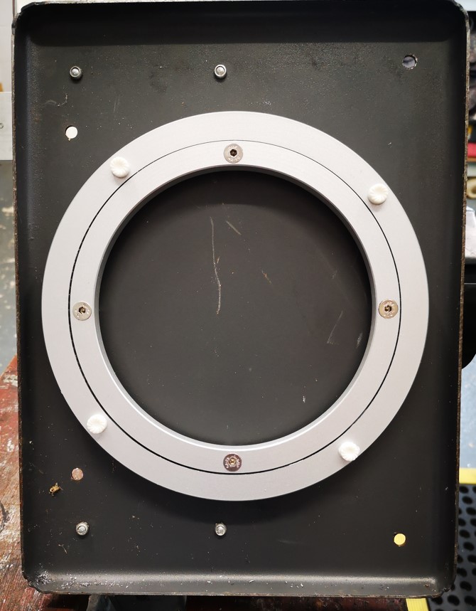
Bottom View with the Lazy Susan ring in place
Tap the holes in the outer ring M6. These are already 5mm clearance so they can be tapped without drilling out.
Cut the baseboard to size. This can be rectangular or circular and from whatever material you have to hand. Offer the ring to the baseboard so it sits centrally and spot through the four M6 tapped holes. Drill these through at 6.5mm and countersink the lower side. Note that in theory you could do away with the wooden baseboard but the BK3 then tends to tip forward when you press on the BK3 cutting table.
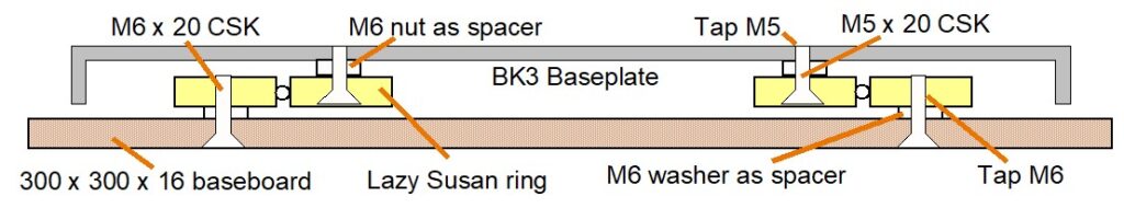
Assembly is a juggling act. The two rings need to be spaced off from the BK3 baseplate and from the new baseboard. I used M6 nuts over the M5 screws as the spacers for the inner ring. I used a single M6 washer on each screw to space off outer ring on the baseboard. Fitting these washer is the main juggling act. To make life easier I dab glued the washers in place on the inside face of the baseboard. Here is a simple sketch of the construction.
That completes what is a simple modification using a Lazy Susan ring and from my point of view it dramatically adds to the usability of the BK3.
BK3 with rotating baseplate
I have added this modification to my compendium write up of my BK3 modifications. The new version 3 can be downloaded on this link.
Having mentioned the BK3 fence in the Quorn bracket post I realised that I had not posted the details of my fence design for the BK3. The fence and the two sets of bearing based guides make the BK3 a very accurate and dramatically more useful tool for the workshop.
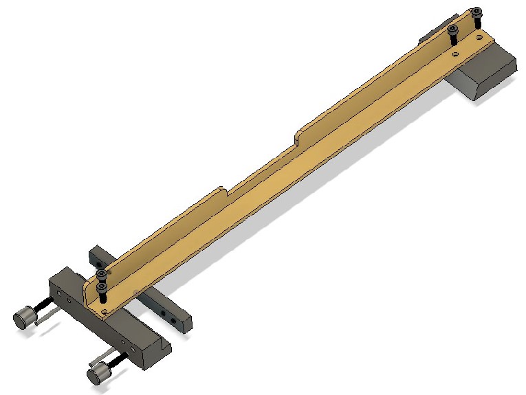
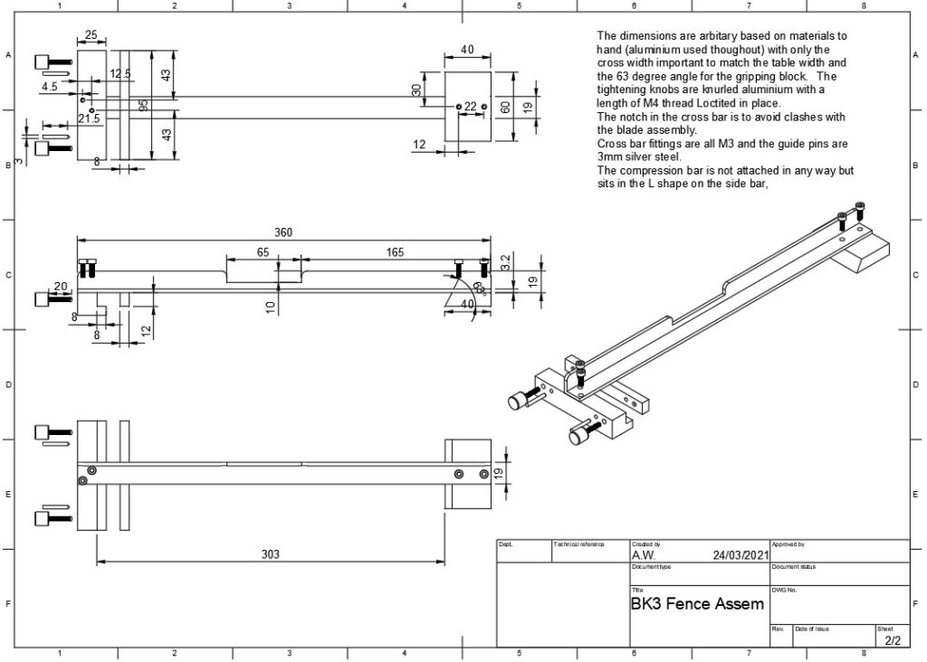
The fence as supplied with the BK3 was tending towards a chocolate fireguard in its usefulness. Here is a Fusion 360 pictorial of my design together with a dimensioned drawing. Both can be downloaded by clicking on the associated PDF file link.
Fusion 360 view of the BK3 fence designDimensioned drawing of the BK3 fence assembly
Here is the link to the Fence Assembly Drawing v4 which has both these views in better detail.
BK3 Angle Setting Fence
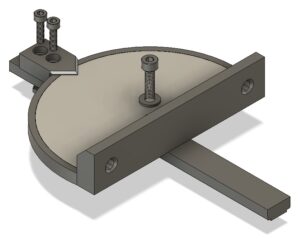
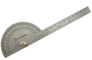
This is a further addition to the BK3 in the form of an angular setting fence. This uses an inset protractor scale liberated from one of the readily available workshop protractors as shown below. These are roughly 92mm diameter.
The body is made from three separately printed 3D parts, the sliding bar, the protractor holder and the pointer block.
The sliding bar has been tweaked in dimensions to snuggly fit the slot in the BK3 table. It has printed nut retaining cavities on the lower surface. For this reason it should be printed upside down. Likewise the pointer block has two locating ribs on the lower surface and debatably should also be printed upside down. This does distort the pointer a little and so might need a clean up post printing. Customise all the retaining screw lengths to ensure they do not protrude below the lower surface of the bar. The rotational locking screw could be made a bit more elegant by making a knurled knob item.
The three STEP files and the Fusion 360 file are in this ZIP file. A full listing of my BK3 modifications can be downloaded as a ZIP file here
Similar or related subjects : –
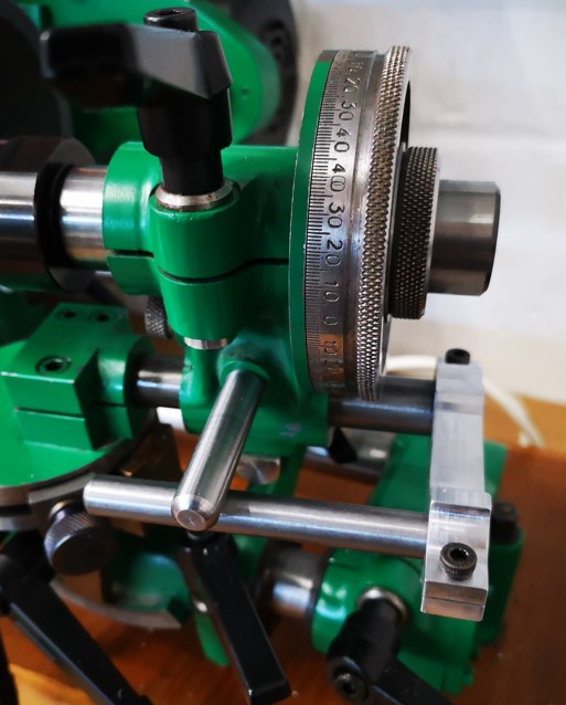
I am slowly getting to understand how to manipulate and use my recently purchased Quorn tool cutter grinder. One frustration that kept cropping up was the workhead assembly slip rotating on the bed bar. This usually happens when there is a need to slide the tool holder head back after a referencing action. This messes up the reference setting.
I chanced upon a thread on the MEW forum where a John P had solved this problem with a parallel support bar assembly. This utilised the 1/4″unused hole in the toolholder side wall. There are a number of ways to fabricate this fixture but the important aspects are that it should be robust and must ensure a parallel motion along the support rod.
The cutter grinder tool head support bar mounted on my Quorn
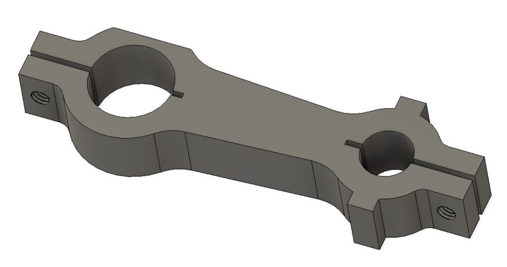
I opted to model the bracket in Fusion 360. As there will be little stress on the bracket in use I opted to mill it from 15mm cast aluminium to give a 12mm finishing depth. Here is the pictorial view from the Fusion desktop.
Fusion 360 model of the Quorn cutter grinder tool head bracket. The bracket measures around 90mm end to end.
The bracket has a 5/8″ hole to match the Quorn table slider rod and a 10mm hole for the new parallel support rod (sorry about the mixed dimensions but my Quorn is an Imperial model and most of my stock is metric).
Side #1 CAM operations are to clean up skim the stock top surface followed by profiling the two holes and the outside shape. Side #2 is to invert the model and deck the excess material. The clamping slots, the flat adjacent to the 5/8″ hole and the M4 tapped holes are all supressed in the CAM and manually cut post CNC operations.
The model has two tabs adjacent to the 10mm hole. These have no relevance to the use of the bracket but are there to make the width of the model equal. This negates the need to use soft jaws to hold the model when undertaking side 2 operations to deck off the excess stock material. The decking brings the model to 10mm finishing depth. These two tabs could be ground off afterwards if desired.
I did consider grub screw clamping of both bars but there was a danger of deforming the associated bars. It was easier and more elegant to design slot clamps into the Fusion model. The clamping slits were cut post CNC machining on my BK3 bandsaw. (Try cutting straight slots on a BK3 without a decent fence and support bearings.) The parallel nature of the finished model width as mentioned above makes this a simple process against the bandsaw fence.
The two M4 clamping screw holes are drilled prior to the slots being cut. The holes are drilled 3.3mm through and then M4 through threaded. After the slots are cut one half of each hole is clearance drilled to M4.
The flat adjacent to the 5/8″ hole is the last ‘after CNC’ machining operation. This flat gives the clearance needed to allow the bracket to slide under the Quorn toolholder referencing dial.
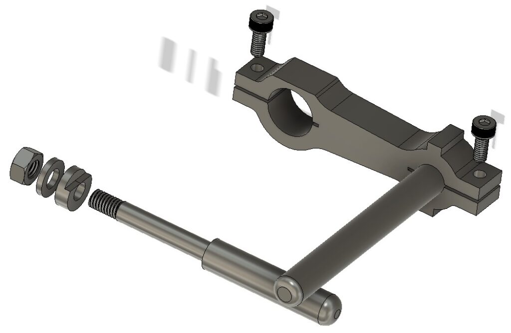
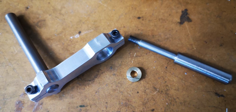
The gliding bar is mounted in the spare hole in the tool holder side wall. This hole in my Quorn had been drilled 1/4″. The rod profile was turned with a centre from 10mm silver steel to have the 1/4″ section and then a short section threaded M6. Note that I also made a brass washer profiled to match the rear face of the through hole in the body. Like most of the Quorn casting holes this had a step segmented surface aimed at stopping bolt head rotations.
Fusion 360 pictorial view of the assemblyQuorn cutter grinder tool head support components – this shows the bracket with support bar in place, supporting rod and profiled washer.
Mounted on the Quorn, the assembly sat nicely parallel, is very solid and stable and does an excellent job of stopping the head drooping. My frustrations over this aspect of the Quorn are eased for the time being.
If any readers want the Fusion file or dimensioned drawings then add a comment below.
UPDATE : – The bracket should be rigid enough when 3D printed instead of machined from solid. Here is a ZIP file containing the support bar clamp version v5 as a STEP file. All the other parts are straightforward lathe operations.


 This is a further addition to the BK3 in the form of an angular setting fence. This uses an inset protractor scale liberated from one of the readily available workshop protractors as shown below. These are roughly 92mm diameter.
 The body is made from three separately printed 3D parts, the sliding bar, the protractor holder and the pointer block.
The sliding bar has been tweaked in dimensions to snuggly fit the slot in the BK3 table. It has printed nut retaining cavities on the lower surface. For this reason it should be printed upside down. Likewise the pointer block has two locating ribs on the lower surface and debatably should also be printed upside down. This does distort the pointer a little and so might need a clean up post printing. Customise all the retaining screw lengths to ensure they do not protrude below the lower surface of the bar. The rotational locking screw could be made a bit more elegant by making a knurled knob item.
The body is made from three separately printed 3D parts, the sliding bar, the protractor holder and the pointer block.
The sliding bar has been tweaked in dimensions to snuggly fit the slot in the BK3 table. It has printed nut retaining cavities on the lower surface. For this reason it should be printed upside down. Likewise the pointer block has two locating ribs on the lower surface and debatably should also be printed upside down. This does distort the pointer a little and so might need a clean up post printing. Customise all the retaining screw lengths to ensure they do not protrude below the lower surface of the bar. The rotational locking screw could be made a bit more elegant by making a knurled knob item.