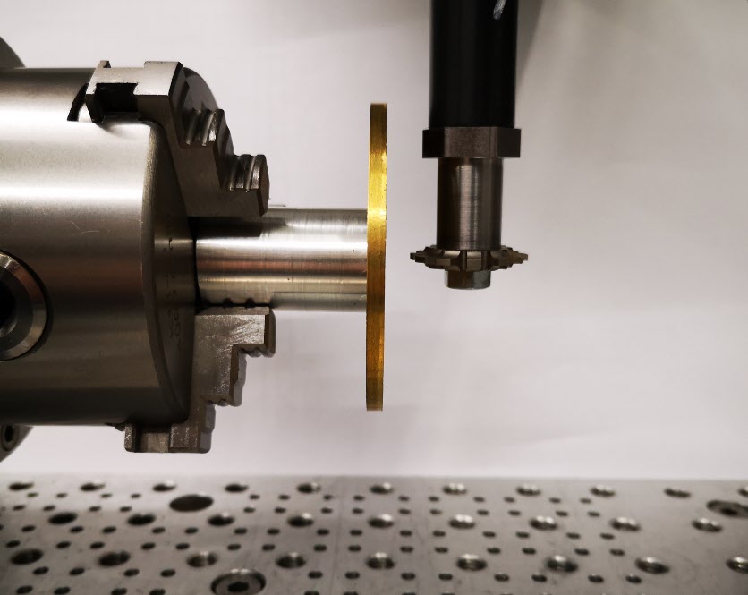
It has been a thoughtful morning on the Tormach wheel cutting setup.
In order to cut clock wheels the first step is that I need to be able to set the cycloidal cutter centre line accurately on the centre line of the blank brass diameter. See the picture and description below.

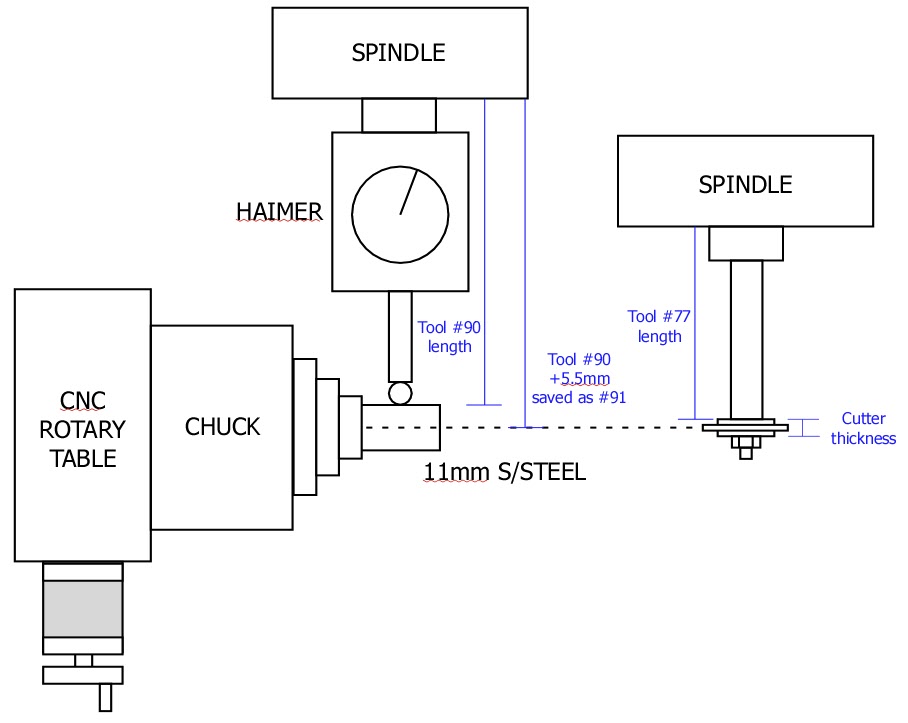
From previous posts you will know I have got the chuck securely and centrally mounted on the CNC rotary table and this assembly is in turn rigidly fixed on the tooling table. The position of the centre line of the chuck is now fixed relative to the tooling plate on the bed. The chuck and rotary table mounting bracket is sufficiently Woody over engineered to hopefully be repeatable. Likewise the distance from the spindle to the chuck can be repeatably zeroed using the Haimer and its associated tool table entry (#90).
Expanding this a little, if I put my favourite piece of 11mm diameter silver steel in the chuck and bring the Haimer down to contact it, rock the Haimer back and forth in Y to get the steel diameter peak, I can get a Z zero reading to the top of the steel. By creating a new entry in the Tormach tool table (#91) which is the Haimer length plus 5.5mm (the radius of the silver steel) I can use this virtual length stored as a new tool #91 to allow me to set the Haimer on the silver steel while actually giving me Z0 on the centre line of the chuck. So far so good.
As you might have read from an earlier post, the idea of using the Tormach Slitting Saw arbor to hold my cycloidal cutters would in theory create a repeatable tool length to the centre line of the cycloidal cutter teeth. Having this as a tool table set up in the Tormach would simplify setting the cutter centre to the centre line of the chuck and therefore the centre line of the wheel blank being cut. This is where the thinking drifted somewhat.
I created a new tool table entry (#77) that was the length of the saw arbor to the shoulder that the cycloidal cutter fastens against. I thought I could then follow the same routine as detailed above and add to this length the half thickness of the cutter and create a new tool table entry to match. This would once again create a length which would give the centre line of the cycloidal cutter.
That was fine until I measured my tray of cycloidal cutters to see what the thickness of the cutters were …… sadly consistent they are not. There seems to be no standard by manufacturer or diameter. I have cutters with thicknesses from 3mm through to 7mm. I could create a new tool table entry for each thickness but this is a recipe for a mistake when selecting the correct tool table entry for the cutter being used.
The simple solution I think is to use slitting saw arbor tool table length (#77) as the initial setting length to Z0 and then do a G0 Z-x.xx where x.xx is the half thickness of the cutter being used. Once Z has dropped to this reading the Z axis can be re-zeroed to run the wheel in question with the cutter in question now sitting on its centre line on the centre line of the chuck.

I hope that all makes sense …. I could of course just eyeball it and not try to be so fussy but when you have the tools to make things easier you might as well use them. I also need to look after my precious piece of 11mm diameter silver steel.
Similar or related subjects : –
- Arduino Processor Reference Clock Accuracy
- 3D Printed Length Gauge for In Barrel Mainsprings
- The “Modern Clock” by Goodrich
- A Very Old Burgess Bandsaw
- Microset Timer interface using Fusion 360 3D model with Fusion Electrical
- Try again after update completes Fusion 360 Error Message
- Clock adjuster rod for measuring spring and fusee drive power
- Engineering Video Favourites Updated List
- Update notes on modifications to the Devon Sea Clock
- Burgess BK3 replacement lower blade guide

