Sindoh 3DWOX filament feed upgrade

Open Filament guide tube and adapters

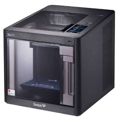
I recently posted about the conversion of our Sindoh 3DWOX 3D printers to allow open source filament use.   One benefit of the conversion is that it allows the filament reel to sit in an external reel box such as a ‘hot box’ dryer from where it is fed direct into the printer. This has resulted in filament being fed much more reliable than it had been using the printer internal cassette system.

On my setup I had a couple of clangs where the exposed filament between the ‘hot box’ and the printer got knocked and damaged.   My solution to this has been to 3D print two filament interfaces to allow a PTFE protective feed tube to be used.

The first of these printed interfaces is a push fit into the Sindoh printed adapter.   The Sindoh adapter performs two functions in the absence of the printer cassette.   It provides a guide to feed the filament into the printer and also overrides the filament detector flap.   The filament feed aperture in the Sindoh adapter is quite wide and I designed my printed part to push into their guide and provide a 2mm feed hole to more accurately ‘aim’ the filament. This feed hole enlarges to a 4mm section that is a push fit grip on 4mm PTFE tube.  Note that dependent on print quality you might have to open out this hole and the 2mm hole to suit the OD of the PTFE tube and the filament. Be careful as the 4mm section does not go all the way through the print leaving a short inner 2mm section.  

The 3D printed adapter on the ‘hot box’ mounts a M6 threaded pneumatic fitting that grips the end of the PTFE tube.   This is fixed over the existing ‘hot box’ exit hole and aims the PTFE tube exit downwards.  I drilled and tapped four M3 mounting holes in the plastic wall of the box base wall to mount the adapter. It sits straddling the base/lid interface line.   This allows the box lid to still be opened. The images below show the Fusion screen shots and the final connected assembly.

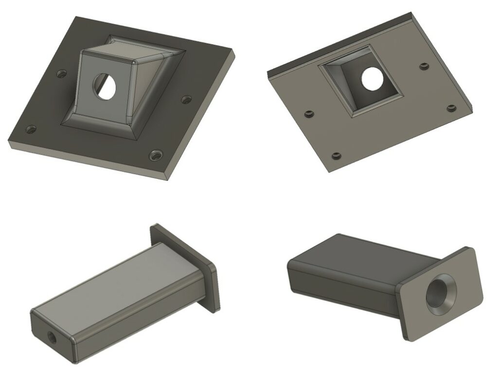
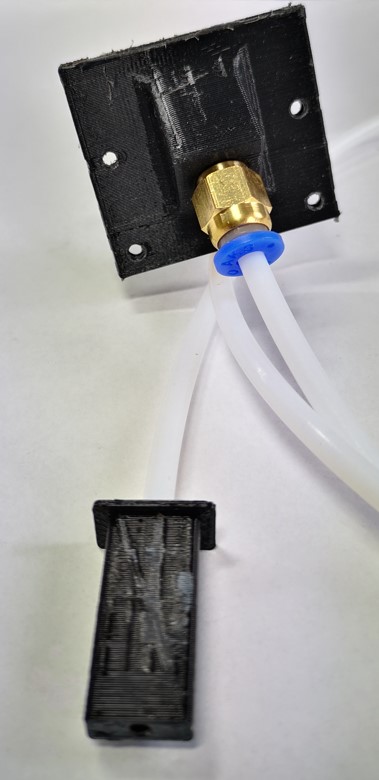
The solution works very well. The length of PTFE tube can be tweaked to suit the physical relationship between the printer and the ‘hot box’.   The tube also gives added moisture protection to the filament when it could be exposed to humid air between printer runs.

These two small adapters have made the filament feed much more professional and the new arrangement has removed the danger of accidental filament damage.

The only problem with external feed to the Sindoh is that the door on the printer can no longer be closed so I need to work on a plan where to drill a suitable slot in the door….

The link below is a ZIP file with the associated files as both Fusion 360 and STLs plus the Sindoh open filament adapter files which were part of the Open Source documentation.

Links to similar or related post are listed below : –

Sindoh DP200 conversion to Open Material

At last a solution for alternative filaments

My Sindoh DP300 has given me reliable, good quality 3D prints since I purchased it in 2017. The DP200 was probably one of the best printers around at that time and had a reputation for simple out of the box operation for those with little or no 3D printing experience (aka me). As a result of this I recommended it to friends and family and collectively we have a number of DP200s in service.

The only frustration we have had since then is the inability to use 3rd party filaments. My understanding is that being an early machine, Sindoh was cautious about the prospect of owners trying to use more advanced filaments and potentially damaging the extruder nozzle. This would have opened the floodgates for warranty claims. Sindoh’s solution to block the use of third party filaments was to issue each reel of their own branded filament with a small PCB personality card. This needed to be mounted in the filament cassette and verified that the filament was legit. The PCB module also recorded the consumption of filament from the reel. I can understand why Sindoh opted for this approach. We did not have an issue with this. Sindoh filament was not dramatically different in price and was readily available and always delivered good quality prints.

As time has progressed, Sindoh has relaxed this restriction on their later models allowing third party filaments to be used. This left the DP200 a little isolated and totally dependent on sourcing the Sindoh filament. During lockdown there was a heavy demand on filament from all sources and like others, their filament went up in price. It also became very difficult to source. This problem has continued albeit not quite as extreme, but it has certainly become difficult to source at a realistic price. As mentioned we have a number of DP200s within family and friends so this has been a continuing frustration.

Out of idle curiosity, I recently emailed a query about this to the Sindoh support team. In my experience they had always been very efficient in responding to cries for help. To my surprise there was a message in my inbox next day with two firmware updates for the DP200 to allow Open Material operation.

On completion of the update process we now have our DP200s able to take filament from the internal cassette or from an external feed box without the need for the chip card. The upgrade was well documented and easy to do. We are very grateful to Sindoh for this support.

There are disclaimers associated with this upgrade. Sindoh is rightly cautious about offering this as a general release. The upgrade infringes the DP200 warranty and use of anything other than PLA and ABS is clearly not recommended. Sindoh also request that the upgrade is not made freely available as a download so I’m sorry that I cannot offer it via my blog. I get the impression that each and every request for the upgrade seems to be treated on its own merits by Sindoh.

From our point of view we are more than pleased to be able to source third party filament for use in our DP200s. I got the impression that my DP200 had perhaps gone into a big sulk when my Qidi ifast arrived. Hopefully the workshop karma will now return.

Links to similar or related post are listed below : –

Workshop resources all coming together like clockwork

Another JSN Job ?

You know how I keep on going on about how solutions to problems are often solved by coming at them from different and often unconventional directions, by utilising and marrying available resources ? It was a philosophy that I encouraged in my team while running my business and it has carried over into my way of working in retirement.   A recent job brought his home to me.

A client had a very old clock that had had a new barrel wheel made and fitted but the clock would not run for more than a few minutes.   There appeared to be an incompatibility either between the modulus of the new wheel and its mating pinion or the shape of the original pinion did not match the shape of the new wheel. 

If you spun the barrel wheel you could feel the resistance build up as the synchronisation between the two profiles drifted out.   Adding extra weight to the barrel helped but did not solve the problem.

So what to do ?   

The barrel wheel was serious engineering and I did not fancy making a new one.   The existing mating pinion was a seven leaf format and its leaves were what you might call pear drop shaped rather than the expected profile.  The pinion arbor had a 72 tooth wheel driving the next part of the clock train but we did have a spare one of these to hand from the minute dial.

Calculations from the geometry of the barrel wheel resulted in a modulus        figure of 1.86.  A rather large value and not one that conventional cutters are readily available for.  The pinion was perhaps something that could be drawn in Fusion 360 and then made on my Tormach CNC PCNC440 milling machine.   The only snag was that the profile needed on the pinion would likely be weird and the world’s supply of brass could diminish rapidly while getting the profile correct.

Using Gearwheel Designer I created what would be the expected profile for a 7 leaf pinion with a modulus of 1.86.  This was exported as a DXF line drawing into Fusion 360.  This outline was extruded in Fusion into a 3D design and a boss was added to mount the 72 tooth wheel. 

The design was 3D printed on my Sindoh 3DWOX printer and was mounted on a 6mm silver steel arbor.   I added a driving disc that interlocked with the printed pinion and the crossings on the wheel to drive the assembly.  Surprise surprise it didn’t run but it did mirror the regular pattern of stiffness of the original pinion. 

Original arbor , pinion and wheel with the driving disc and a test profile
The original arbor, pinion and wheel together with the driving disc and a 3D printed pinion test profile. The driving disc has screws to lock it to the wheel and two protruding pins to lock into the 3D printed pinion profile under test. The 3D printed profile was a tight pressure fit onto the new 6mm arbor.

I now had the test bed for quickly making and testing different pinion profiles. There followed a number of hours watching the engagement progression of the profile of the pinion into the barrel wheel and then trying to conceive a profile for the pinion that might run. 

3D printed test profiles
Various trial profiles and the temporary driving disc to engage with the 72 tooth wheel


Test pinion in place on the new arbor
A test pinion in place showing the 72 tooth wheel and the driving disc

Fusion 360 made this process so easy and round 10 printed test profiles later I had success with a clock that now ran.    The driving weight on the barrel was around 11kg and it looked to be worthwhile wasting some brass making a ‘proper’ one. 

I took the 3D design and produced CAM code in Fusion.   This would cut the profile ‘on end’ using an adaptive first cut with a 4mm end mill followed by rest machining the remaining material with a 2mm end mill. 

Images of the Fusion 360 process of creating the new 7 leaf pinion
The Fusion 3D model of the pinion, the CAM simulation of the leaf cutting, first adaptive cut of the leaves and rest machining final pinion

The resulting brass pinion was mounted on the arbor and the clock ran with a strong beat.   As expected the brass pinion gave less surface to surface resistance than the 3D printed part and the barrel driving weight was now able to be reduced down to 6.25kg.

new pinion mounted in the clock
The finished pinion mounted in the clock on the new arbor

I ran my Microset Timer on the clock overnight and had a first off timing error of 5 minutes per day which was fixable with a pendulum tweak. The movement had an instability of a few seconds per day which was quite astonishing.

The conclusion of the experience is that at first glance this seemed like a conventional pinion cutting exercise …. but M1.86 cutters are not readily available.   If a cutter could have been found at less than a King’s Ransom it is likely that the resulting conventional profile would have been wrong to match the barrel wheel.   

The alternative route that was taken of Gearwheel Designer to Fusion to 3D print to Fusion CAM to CNC machining solved the problem albeit with a final weird profile.    The purists and traditionalists will groan.   There will be a gnashing of teeth and a pulling out of hair. 

Does it really matter if the result is new life for what could have become a heap of scrap metal ?

Similar or related subjects : –

Replacing the Sindoh 3D Printer Bed Lamination Sheet

I have had my Sindoh 3D printer for quite a while and it is a lovely machine to use in conjunction with Fusion 360.   I have printed all manner of items for the workshop, for projects and for friends and family.

For some time it has been a problem to print objects central on the bed.   While they would print OK, they are reluctant to come away from the bed surface and then having removed them from the bed, the raft would be very reluctant to leave the printed object.   I have got round this by offsetting the print position in X and Y on the table.   If I have a large object to print that overlaps the problem area I sprinkle talcum powder on the bed surface to ease freeing the object from the bed but this does not help the raft removal.

The print bed is an aluminium sheet that slides in and out of the machine.  This has a PTFE style laminated coating sheet held in place by adhesive. If I inspect the centre of the plate I can see the clear outline of bubbles under the lamination sheet.   These have got worse as time has gone by.  I imagine the bubbles create a finite air gap that upsets the temperature stability of the plate in the damaged area.

The situation had reached a frustrating peak today and lead to me totally removed the laminating sheet to leave bare aluminium.   The printer could not cope with bare ally and the PLA would not stick.  Some other laminating medium was going to be needed.

I had seen discussion regarding the use of what we in the UK call Masking Tape as a laminating medium.   I use 3M Blue Multipurpose Builders Masking Tape for Super Glue mounting of stock on the milling machine.   Having this to hand, I thought it worth a try. The tape is 48mm wide so I had to fix a number of strips across the plate to cover it completely and then trim the edges.  As you can see below, I didn’t quite get them parallel and butted to each other I was keen to run a test print.

Maybe I was lucky but the job came off the tape easily and the raft pulled off straightaway with no damage to the print.   The tape hasn’t bubbled or coming  off in any way so it looks good.

builders tape on Sindoh 3D printer bedplate
3M Blue Builders Tape on my Sindoh print bed

I am not sure how long the tape is going to last but I have got a full reel to keep swapping it out.

Update :  17/6/2021

I have been using the blue tape bed coating for over a year now with no problems other than an occasional replacement when it gets torn.

The other thing worth noting is that if your bed clips break there is an excellent replacement print model to download here

https://www.thingiverse.com/thing:4487138

Similar or related subjects : –

Sindoh 3DWOX DP200 Raft Printing Problem

My close friend in France also has a Sindoh 3DWOX DP200 3D printer.  We bought them at a similar time.  He has probably been a busier user of the machine.   He has designed and making a very complex camera mount for tracking celestial objects.  He is using an Arduino as the controller and has never written code before.  He is having fun and keeping his brain stimulated.

A few weeks ago he reported that the raft that the machine was laying down before printing objects was not uniform and had ‘holes’ in it.   The result was that the PLA being extruded for the object being printed, would droop down into the void in the raft and spoil the finish of the object while also making it hard to separate from the raft afterwards.

We swapped ideas remotely about what might be the cause and tried various tests and experiments but to no avail.

As it happened a few days ago we were travelling down into France and calling in to see him for lunch so I had a chance to see the problem first hand.   More head scratching until …. I had the printer bed in my hand near the window and the sunlight caught the surface of the plastic laminated to the metal bed.   My eye caught a slight bubble in the plastic surface where the adhesive bonding the plastic to the metal had presumably parted company.   This was the problem !   The air bubble, small though it was, was causing a discontinuity in the bed temperature profile leading to the PLA not flowing from the nozzle correctly.

We ran a print and put the object on a different area of the bed where there was no bubbling or scratches and the raft and the print were good.

New bed plate ordered ….

Similar or related subjects : –

Verified by ExactMetrics