More use of 3D printed Soft Jaws
A few posts ago I talked about using 3D printed soft jaws for work holding in CNC operations. This method does not replace conventional aluminium soft jaws where high accuracy machining operations are to take place. Instead it is intended to allow second side ‘decking’ of what would have been excess stock on the material blank that had been used for work holding.
I am currently creating missing components for a Thwaites turret clock. I had finished the pallets and I now moved onto the new escape wheel. The design was created in Fusion 360 and integrated the pallets and the escape wheel together so the critical geometry was compatible.
The brass blank for the escape wheel was a 1/4″ brass block which I managed to hold tightly in the machine vice with a 1mm thickness of gripping stock. (I don’t have Tallon grips or similar so I have to be generous). I machined the wheel and was left with this 1mm to skim off the reverse side of the wheel.
I did not want the teeth on the new wheel to get damaged when gripped in the vice so the 3D printed soft jaw concept appealed. The PLA would provide grip. The teeth on the wheel could bite into the PLA without suffering any damage.
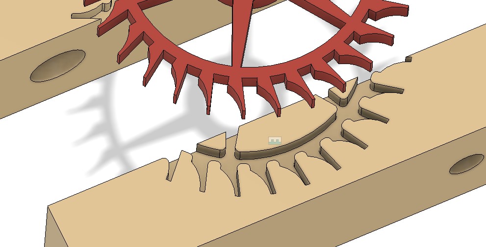
I had already created a single blank soft jaw In Fusion 360 for the previous pallet holding job. This like it would be fine to accommodate the wheel dimensions. I simply had to import two of these into the new soft jaw design (not forgetting to ‘Break the Link’ so the jaw models could be edited). I projected the wheel onto the soft jaw’s face and added a 0.2mm positive offset border. I almost made the mistake of forgetting to invert the wheel as the soft jaw image must be a mirror of the Fusion top side view of the design to be gripped.
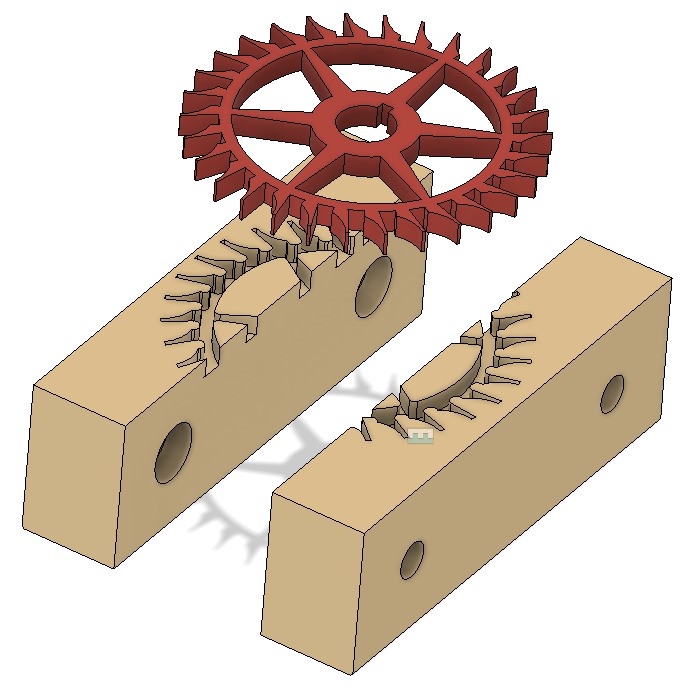
The finished brass wheel did not accurately reflect the geometry of the Fusion design. This is because the resolution of the tight corner CNC operations were limited to tool sizes. I added fillets to all the ‘sharp’ edges in the soft jaw image to accommodate this. I also had to do some tweaking of the inter jaw spacing 3D joint to reflect the wheel diameter and the amount of grip I judged might be needed.
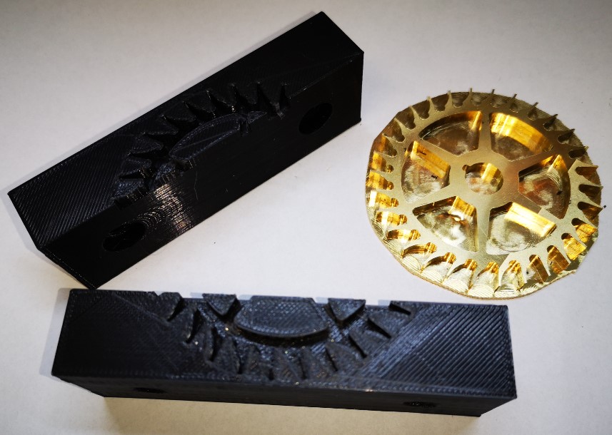
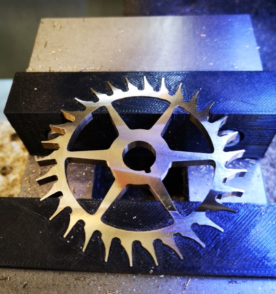
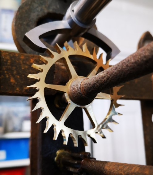
I am really warming to this technique. It is quick and easy to implement and any mistakes can be quickly rectified with a new 3D print without having to remake aluminium versions. I like it and recommend it.
Similar or related subjects : –
- Arduino Processor Reference Clock Accuracy
- 3D Printed Length Gauge for In Barrel Mainsprings
- The “Modern Clock” by Goodrich
- Microset Timer interface using Fusion 360 3D model with Fusion Electrical
- Clock adjuster rod for measuring spring and fusee drive power
- Update notes on modifications to the Devon Sea Clock
- A church clock problem and lockdown timekeeping
- Repairs to an ancient Thwaites clock completed
- Vice soft jaws and then soft soft vice jaws
- Workshop resources all coming together like clockwork

