Some time ago I documented my implementation of the Clough42 Electronic Leadscrew on my Myford Super 7 Big Bore lathe. I also wrote up adding thrust bearings to the top slide and cross slide adjusters. What remained outstanding was adding thrust bearings to the leadscrew. While there is a commercial kit from Hemmingway Kits to install these, my implementation of the ELS involved a direct drive to the leadscrew at the tailstock end of the bed and made things difficult – I ran out of length on the leadscrew.
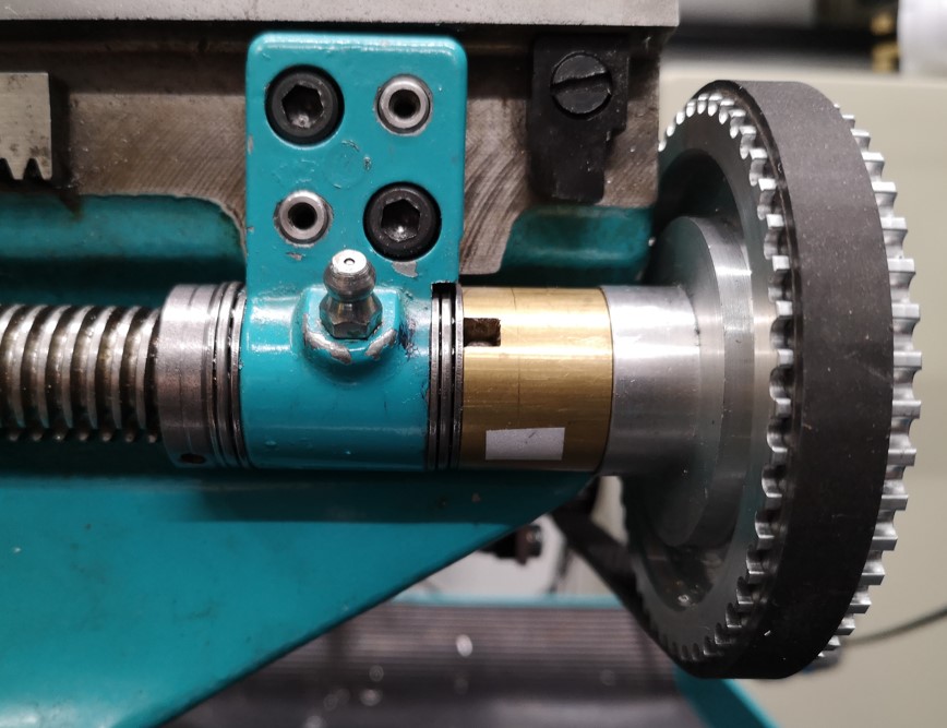
After considering the situation I opted to retain my ELS drive concept and gain space for the bearings by shaving metal from the Myford leadscrew bracket. It is not an ideal modification as I am always very reticent about physically changing the structure of my machines. Despite this I have to say it seems to have paid off and I now have a very stable and repeatable leadscrew feed from the ELS. Here is a photo of the result.

I have added details of the modification to the original thrust bearing write up and this can be downloaded as a PDF from the link below.
Myford Super 7 Thrust Bearing Mods including leadscrew
Similar or related subjects : –
- Eccentric Engineering Turnado freehand turning tool
- Rotring 300 2mm clutch pencil modification
- Kindling Cracker – a safer option
- SINO SDS2MS DRO repair
- A useful Amazon sourced small item storage system
- 3D Printed Threads Modelled in Fusion 360
- Three axis stepper controller PCB in stock
- Myford Super 7 Large Bore depth stop
- Tangential Lathe Toolholder for Myford Super 7
- Hemmingway Sensitive Knurling Tool


