Better to have it and not need it etc
I have had an Ingram (1905) mechanical clock in for service. A simple clean and set to time which went to plan (for a change). The only niggle was one of the four tapered wooden pegs that hold the dial and movement into the wall case was missing. I could have 3D printed a tasteless replacement but my conscience would not let me stoop that low. It needed to be a wooden part with similar geometry.
Quite some time ago I had ordered a pair of Diamond Tool Holders from Eccentric Engineering in Australia and at the time Gary was doing a special deal on his Turnado hand turning tool. As I was going to be paying a significant carriage cost I decided to consolidate and offset this with the Turnado kit.
On receipt of the package I played with the Turnado but had no needing projects at that time. It is well thought out and allows freehand turning either as freeform movements or movement against a template profile or with a pantograph. Here is a link to Gary’s sales video.
In the process of considering making a 3D printed version of the peg I had dimensioned and drawn a 3D model in Fusion.
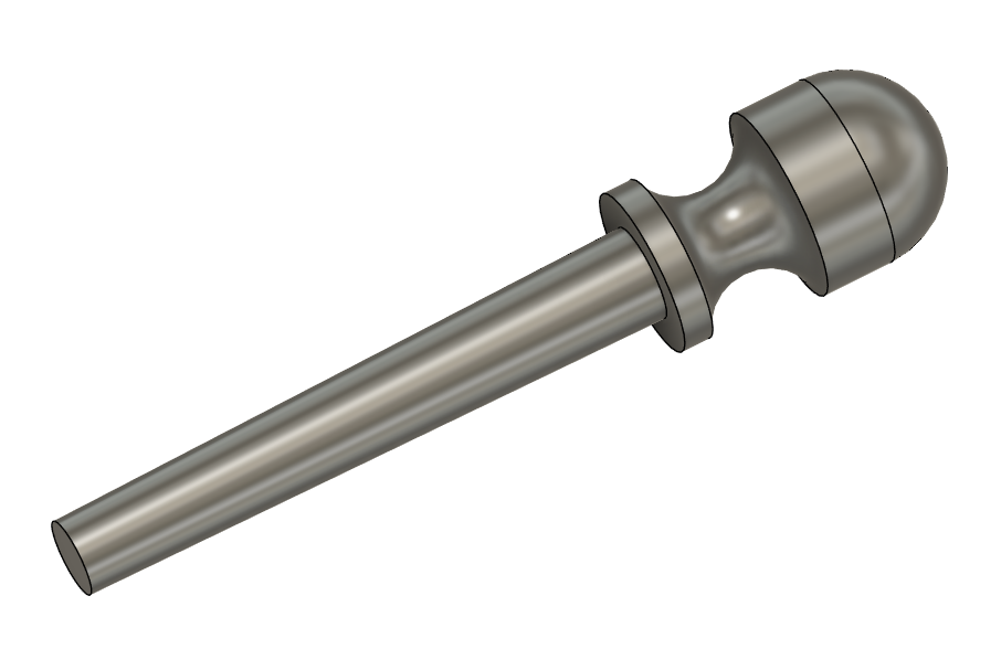
Taking the 3D model and opening it in Fusion Drawing mode gave me a 1:1, 2D PDF drawing of the peg. I cut out the 2D image and stuck this to a piece of aluminium with 3M Spray Mount and then nibbled and filed the aluminium to the peg drawing profile.
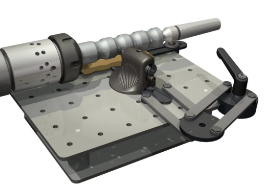
The profile template was mounted on the Turnado working table and the shape profiled into a piece of 18mm dowel using the Turnado tool on its pantagraph following my profile.
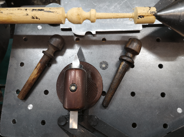
Here is a posed picture of the setup showing the Turnado tool and table with my profile plate, for effect a first attempt at the peg is sitting in the chuck between centres with the original peg (LHS) and the finished peg (RHS). Not quite a total match but more than functional.
Absolute magic. A really useful asset. I just need to remember I have it ….
As Jimmy Diresta would say “Better to have it and not need it than need it and not have it”
Links to similar or related post are listed below : –
- Eccentric Engineering Turnado freehand turning tool
- Rotring 300 2mm clutch pencil modification
- Kindling Cracker – a safer option
- SINO SDS2MS DRO repair
- A useful Amazon sourced small item storage system
- 3D Printed Threads Modelled in Fusion 360
- Three axis stepper controller PCB in stock
- Myford Super 7 Large Bore depth stop
- Tangential Lathe Toolholder for Myford Super 7
- Hemmingway Sensitive Knurling Tool