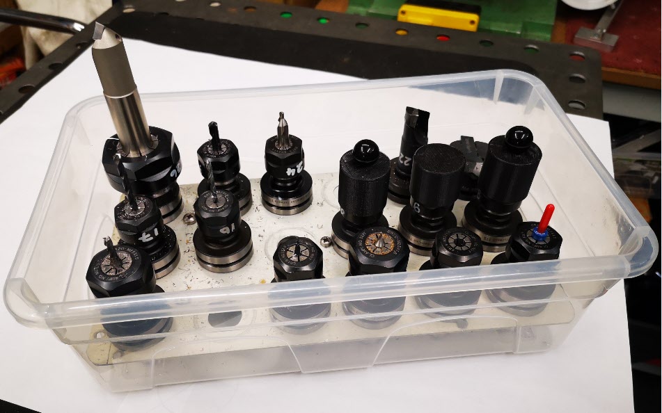
Some time ago I posted a note about using the Spacemaster 5L storage boxes for all things workshop. These are an incredibly versatile size and I admit to having a plethora of them sprinkled around the workshop including use for storage of my Tormach TTS tooling collets.
On the subject of TTS collets, I grew weary of having to repaint the tool number on the side of the collets and have migrated instead to printed labels.
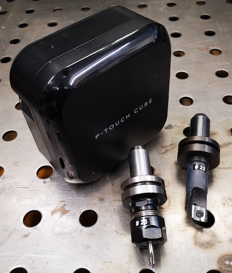
These are printed on a Brother P-Touch Cube printer using their 6mm White on Black tape stock. These look very professional and time will tell how robust they are when subjected to cutting fluid. The P-Touch is nice in that it is battery powered and connects on Bluetooth so I can print ‘on the go’ from the Android App. The only frustration with the P-Touch is that it wastes around 2cms of tape at the beginning of each label print. I minimise this wastage by concatenating all my labels into one long print and then cut them up individually with scissors after printing.
The right hand side oiler for the Z axis on my 440 has always had a poor oil feed to the slideway. I had tried to clear all the pipework that is easily accessible but with no improvement. I was conscious that deeply embedded in the spindle assembly was an oil manifold that fed the left and right slideways and the ball screw. Could this be the source of the problem and how was I going to get at it without a major strip down of the Z axis spindle assembly ?
Looking down from the top of the spindle assembly I could just see the manifold in a hole in the casting. If I could get to this I might just be able to work on it without a major strip down.
First of all an apology that I do not have any photographs of what follows as I was so engrossed and so grubby that I left my phone secure and out of the way. The process will become obvious as you progress and is not overtly difficult.
The stripping process was to remove the two screws holding the door interlock switch, remove the four screws holding the wrap round cover, remove the holding pin on the power drawbar and remove the two bolts holding the spindle motor. With all these fixings and parts freed off it is possible to lift the outer cover up and over out of the way and to lay the spindle motor inside it. It is tight to shimmy the cover around the power drawbar body flange but it is possible without removing the drawbar piston assembly.
With all this removed it fully reveals and gives access to the cavity containing the manifold. It is a short term joy because it is pretty much impossible to undo the right hand side oil feed as this is from the end of the manifold.
Light bulb moment – if I drilled two 6mm holes in the assembly casting opposite the two hex head screws that are holding the manifold in place, I could get a hex driver T bar to remove these screws and free the manifold from the casting wall. This would allow the manifold to be moved to work on it.
Here is a drawing to help locate the two holes giving the distance from the back and bottom of the casting. (The lower black and blue assembly is my fogbuster mounting).
Once the manifold is free to be moved around it is possible to remove the right hand feed pipe and remove the associated length of pipework to clean it. I found the manifold end of the pipe had not been cleanly cut and was restricting oil flow.
A word of warning – the oil feed to the ball screw is a semi rigid pipe and this terminates in the side of the ball screw. Do not overstress this length of pipework or there will be tears.
Assembly is the reverse process. Apologies once again for the lack of supporting pictures.
I can report my right hand side Z axis slideway oil flow is much improved.
When I bought my Tormach PCNC440 in 2016 I included the enclosure kit in my order. On receipt I thought that fitting the enclosure would dominate the size of the workshop so I never got round to fitting it. It has sat in its shipping box since then. I have consequently shared quite a bit of my swarf (chips) with long suffering family.
After a recent (particularly heavy) CNC run I had a serious covering of swarf in the machine tray and because I had no enclosure round the mill, I had quite a lot distributed further afield (i.e. into the house). Domestic peace was becoming an issue. Time to do something about it.
Out came the enclosure kit, cobwebs dusted off and around three hours later I had the enclosure fitted. I have to say it looks good and does not overpower the workshop as I thought it would. My wife is impressed and says it looks a more professional machine and ‘if you had it why didn’t you fit it before now’ ?
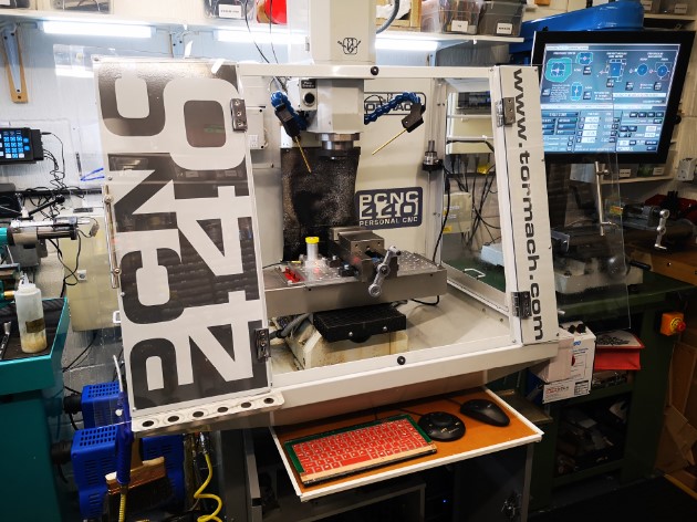
The picture above shows the enclosure mounted on my PCNC440 with the monitor in the original position before fitting the extension arm to the ISO bracket. The keyboard tray uses a domestic drawer rail mounted on the top of the standard Tormach cabinet. My recently fitted dual fogbuster system and my Hall Effect based tool height setter (yellow top) are visible.
The fitting did however create some follow up problems.
My control monitor had up to now been mounted on the side of the 440 on a standard ISO TV mount. With the enclosure fitted this meant it was ’round the side’ and difficult to get to. I debated a new long reach ISO but they are expensive. Plan B was to make something. I rummaged around in my aluminium stock and with the help of Fusion 360 came up with a seriously overengineered extension arm to add to the existing ISO mount. This would allow the monitor to move forward to be in reach at the front of the mill.
My seriously over engineered extension bracket to move the ISO mounting of the monitor more to the front of the 440
This bracket became the first CNC job to run after fitting the enclosure. I am pleased to say it was the cleanest my workshop floor had ever been after running a job.
Having fitted the new bracket and mounted the monitor, all the cables needed extending. Fortunately I had had the foresight on my original order to include the extension cable kit. As a result I only had to extend the power supply lead from the monitor 12V ‘brick’ supply.
The second issue was where to mount my ITTP probe as this had formerly mounted on the side of the 440. With help of some more Fusion design I modelled a corner mount that picked up on the enclosure fastenings.
After that first heavy machining run I noticed for the first time the slight smell of the mist coolant when opening the enclosure doors. Before the enclosure was fitted the smell must have dispersed into the general workshop air. With the enclosure fitted the air was concentrated inside the mill and I only got the smell when sticking my head inside. While it had never been a problem (as far as I can tell …) I thought I should do something about it.
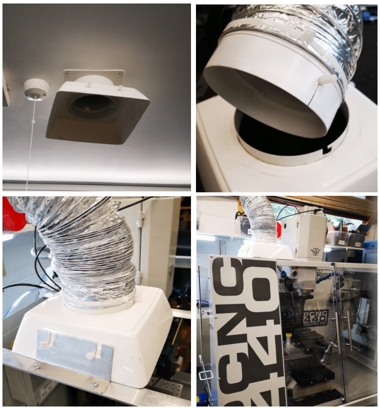
Sometime ago I installed a ceiling extract duct in the workshop. This vents to the outside world via a custom roof tile. Normally the system sits with a flared cowling (made from a cut down flower pot) on the ceiling entry duct. The system normally acts as a background trickle extract. The cunning plan in the design was to use various pipe components to provide bayonet style connection pins (Nylon screws) to allow extension trunking to be used. A bit like a BNC RF connector if this is familiar to you. This would allow me to use an add-on length of expanding flexi trunking to bring the extract nearer to any heavy fumy activity such as welding or oil bath hardening.
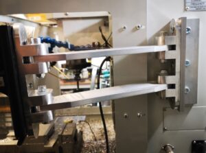
With the use of further scrap odds and ends of aluminium, I mounted a pair of support bars across the top of the new 440 enclosure. These would fix the ducting over the enclosure during heaving CNC sessions. Not a total solution but certainly one that will reduce the general smell of XtremeCut 250C when I stick my head in the enclosure.
Extract system showing ceiling mounting intake, trunking adapter and mounting on my Tormach PCNC440. Note the two Nylon screw protrusions are for a bench mounting clamp when used for welding extraction etc and now used on this new use of the system on the mill.
A good day’s activity with all the issues addressed and domestic bliss hopefully restored.
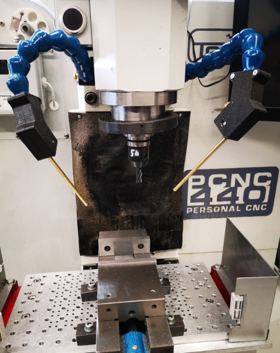
Apart from working on the Thwaites clock parts, I have also done an upgrade to the mounting of my Fogbuster coolant nozzle installation on my Tormach 440. This was triggered after viewing and being impressed by Clough42’s idea. The Fogbuster is a great way to clear swarf and apply coolant. The Fogbuster is normally supplied with a magnetic mounting arm but James’ modification uses LocLine gooseneck components to provide a much more flexible ‘aiming’ capability.
Something to be aware of – James recommends a download from GrabCAD for the 3D files of the two halves of the nozzle holder. These had been uploaded by contributor Br BRB. These were apparently publicly available via GrabCAD. James slightly modified these and was offering them as a free download from his Thingiverse folder. He has since had to remove them for download due to commercial issues. BrBRB has also removed the original files from GrabCAD and is seeking to sell these as finished items. I was lucky to have downloaded the files before the politics cropped up. I still have the downloads.
James also advocates fitting a second identical nozzle to the Fogbuster to avoid coolant and air shadowing. I contacted Fogbuster in California and a very helpful lady called Rachel organised an upgrade kit to provide a second feed from my existing coolant reservoir.
Dual Fogbuster coolant nozzles on Tormach PCNC440 using Clough 42 flexible nozzle idea
It turned out Rachel was from Bristol UK so it is a small world and we had a good chat. I have fitted both nozzles to the Tormach. With a pressure of around 10 to 15 psi, the reservoir feeds both nozzles very well and is a huge improvement in use.
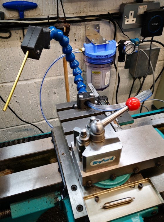
As I was facing a shipping charge from the US I figured I might as well top up the package so I have also splashed out on a baby version of the Fogbuster to fit to my Myford lathe. This uses the same idea but with slightly different mounting that fits into the T Slot on the Myford saddle. I already had the 3D model of the T Slot strip from the ‘bits tray’ installation.
Baby Fogbuster mounted on my Myford Super 7 saddle based on the Clough 42 flexi nozzle idea
Another pair of incremental asset improvements successfully installed. I suppose I had better get on and make something now.
Back to ‘the clock’ …
UPDATE 2 : – The 3D printed ball joint kept working lose on both the milling machine fogbuster mouunts. The more I tightened the screws to grip it tighter, the more the 3D components began to crack and give way. The solution was to fit brass inserts into the 3D prints. Problem solved. Incidentally there is a good review of such inserts on CNC Kitchen.
This is probably not original but worth commenting on. I have a tooling plate on the bed of my Tormach PCNC440. This has a matrix of M8 holes on 25mm spacing together with intermediate 3.7mm tooling pin holes.
Quite often I have a need to set up my work CNC coordinate system (WCS) such that it is centred on one of the M8 holes.
If I want to do a quick and dirty centre on one of these holes then I use the Laser Centring tool as mentioned elsewhere on my blog.
If I need to be a bit more precise then I have a mushroom/top hat shaped disc with shank that is a tight fit in the tapped M8 holes. PathPilot has a number of probing routines and these include finding the centre of a circular object. Simply push the top hat into the desired hole and then probe the disc for centre. You can use an active probe such as the Hallmark ITTP.
If you haven’t got an active probe you can use a Haimer. Simply align the Haimer tip somewhere close to a maximum point on the disc circumference and advance the axis to show a reading on the Haimer. Rock the opposite axis back and forth and watch the Haimer reading to find the high point on the circumference. Zero the axis. Go to the opposite side of the disc and repeat this process and divide the measured diameter by 2 for the disc centre. Repeat on the opposite axis.
(You can use this Haimer rocking back and forth method to find the diameter high point when cross drilling a circular item to fit grub screws etc).
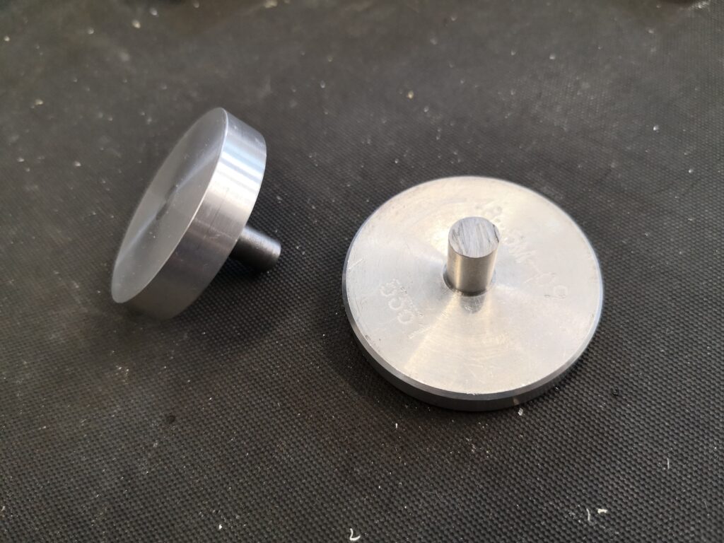
Two examples from my ‘mushroom farm’
The mushrooms are made with a silver steel shank that is skimmed to be a non wobble (how technical is that ..) fit in M8 (~6.8mm) and an aluminium top hat that is superglued in place on the shank. Once the glue has set the top hat is squared up while held in a collet in the lathe. This ensures concentricity with the shank. The disc will now sit flat to the tooling table when the shank is pressed home and perpendicular in the hole.
Clearly the larger the disc diameter the less centring error there will be.
I now have a ‘mushroom farm’ of discs for all manner of hole sizes. It’s not rocket science but as you well know, I am all for a simple (aka lazy) approach. Apologies to all the Grannies out there.