Two important Fusion 360 Preferences tips

One obvious and one more specific

If you already know these Fusion 360 Preferences tips then well done. If not check out below.

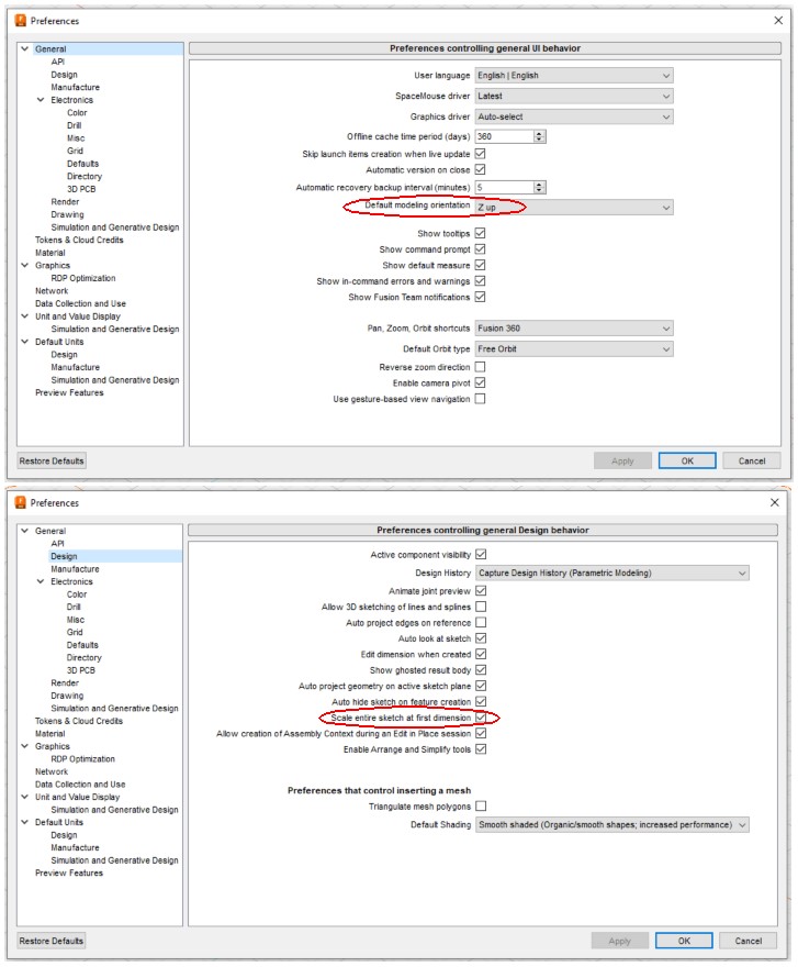
The first one is to set the default orientation to be Z up so your CAM output is already well on the way to being correctly configured.

The second one is not so obvious – scaling the entire sketch based on the first dimension you specify. Suppose you have an object that you want to draw to scale based on a photograph image. If you import this using Insert/Canvas you get a faint image of the photograph over which you can superimpose your sketch. Once you have created the sketch you can then draw a construction line that runs from any two extreme longest points of the sketch. Measure the distance on the real object and then specify this dimension on your sketch. Everything on the sketch will now be scaled accordingly. So useful ….

Probably the best example I have seen of this was by Clough42 in this video about his construction of a depanelizing tool for PCB biscuits. He has done a further video recently using the same technique with dual axis images. This is impressive to watch.

Minor update on the Qidi i-fast to say all is going well and I am getting some very good print results. I am still debating which slicer to run with and do seem to be getting more repeatable prints using Simplify 3D.

Links to similar or related post are listed below : –

Adding thrust bearings to the Myford Super 7 with Clough42 ELS fitted

Some time ago I documented my implementation of the Clough42 Electronic Leadscrew on my Myford Super 7 Big Bore lathe.   I also wrote up adding thrust bearings to the top slide and cross slide adjusters.   What remained outstanding was adding thrust bearings to the leadscrew.  While there is a commercial kit from Hemmingway Kits to install these, my implementation of the ELS involved a direct drive to the leadscrew at the tailstock end of the bed and made things difficult – I ran out of length on the leadscrew.

After considering the situation I opted to retain my ELS drive concept and gain space for the bearings by shaving metal from the Myford leadscrew bracket.  It is not an ideal modification as I am always very reticent about physically changing the structure of my machines.   Despite this I have to say it seems to have paid off and I now have a very stable and repeatable leadscrew feed from the ELS.  Here is a photo of the result.

modification to the leadscrew mounting for adding thrust bearings
The final assembly using the ELS drive concept to the end of the leadscrew and how space was made for thrust bearings to be fitted

I have added details of the modification to the original thrust bearing write up and this can be downloaded as a PDF from the link below.

Myford Super 7 Thrust Bearing Mods including leadscrew

Similar or related subjects : –

First screw threads cut using Clough42 electronic leadscrew

Metric Threads on an Imperial Lathe

You might well have read my write up on how I implemented the Clough42 Electronic Leadscrew on my Myford Super 7 Large Bore lathe.

While I have been successfully using the ELS as an automatic feed, I had put off attempting screw thread cutting.  You know how it is.   Screw cutting is nagging at you to try, but it is on the ‘too difficult’ pile pending other more interesting jobs.  There is always something else to do, so you kid yourself it is justified to put it off until another day.  Well another ‘lockdown’ day dawned and I decided today was the day.   

My experiences are recorded here as a full write up

Screw cutting using the Clough42 ELS

Similar or related subjects : –

Clough42 Electronic Leadscrew Project Implementation Notes

I have been avidly watching Clough42 on YouTube.  James comes over as a really nice guy and his presentation of his projects is excellent.

My principle interest is the Electronic Leadscrew modification to lathes.  When installed this removes all the hassle of gearboxes and look up tables to be able to cut both Imperial and Metric screw threads and to set X axis movement feed rates.

The concept is simple but his implementation is second to none.  A rotary encoder is fitted to the spindle to count revolutions of the chuck and a stepper motor (or servo hybrid) controls the rotation of the leadscrew.  The resulting feed speed is derived from look up tables.  The whole installation is controlled by a Texas Instruments LaunchPad C2000 microcontroller development board.

I have documented how I implemented this on my Myford Super 7 Big Bore lathe and the pdf can be downloaded below.   There is also a ZIP file of all the Fusion related models for either CNC or 3D printing.

Electronic Leadscrew on Myford Super 7

Minor edits added to v3 relating to programming the servo controller

Electronic Leadscrew on Myford Super 7 v3

Electronic Leadscrew Fusion 360 Files

Updates : –

Painted control panel for Clough42 Electronic Leadscrew
Finally got the Clough42 Electronic Leadscrew control panel box painted and rather pleased with the result.

Since installing the ELS I have incorporated thrust bearings on the leadscrew mounting.   This impacts on the coupling to the stepper motor.

Similar or related subjects : –

Verified by ExactMetrics