Jerky Mouse Effects with 3D Connexion SpaceMouse and CadMouse used together

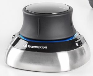
Quite some time ago I posted about the fact that I had bought a package deal of the wireless 3D Connexion SpaceMouse and CadMouse devices.   Since then I have come to cherish the SpaceMouse and would be lost without it.   It makes modelling in Fusion 360 an amazing experience.

3DConnexions Space Mouse

Since using this combination I had been experiencing an irritation with the CadMouse lagging and twitchy/jerky in its action.   This is not always present every time I use the combination of these two devices but you could guarantee it would raise its head when I was in a rush to finish a design.   There has never been a similar issue with the SpaceMouse.   I had searched the forums and tried adjusting various graphic parameters but to no consistent result.

The two devices when bought as a package share the same USB wireless dongle.   Clearly the pair would be timesharing this data link so I thought this might be a data bandwidth issue.  I transferred the dongle to a high speed USB port (the ones with the blue insert).   I can’t say this helped or at least there did not seem to be a correlated improvement with this move.

Of late I have switched the CadMouse off completely and reverted to my Logitech M705 wireless mouse with its associated USB dongle.   Fingers crossed this seems to have solved the problem.  The Logitech behaves well and is responsive to my mouse movements and there is no impact on the SpaceMouse when working on its own into its USB dongle.

Time will tell.

Similar or related subjects : –

3D printed Dremel based TIG Tungsten Grinder

Are you a Dipper also ?

Not being the most proficient TIG welder I sometimes dip the tungsten in the weld pool and contaminate it.   This means a re-grind of the tip.   I don’t have a dedicated grinding wheel so the grinding process has the potential to fundamentally contaminate the tungsten from the wheel while re-grinding.  This got me thinking whether I could use my Dremel with a dedicated grinding wheel that would be reserved just for tungsten grinding.

I decided that my design would be based around my most used two tungsten diameter sizes (1/16” and 1/8”) and I would aim for 15°, 30° and 60° inclusive grinding angles.

I have always been nervous about tungsten dust and even more so knowing that some tungsten materials are radioactive so my design would enclose the grinding process and a viewing window would let me see what was going on.

The design is not ideal because the recommendation for grinding tungsten is to have the grinding striations running in line back down the cone of the point and not around the point.  The final result depends on the speed of the Dremel and the speed of rotation of the tungsten being ground.

Fusion 360 image of the tungsten grinder assembly
Fusion 360 image of the tungsten grinder assembly showing the grinding wheel for reference
Finished view of the Dremel based TIG tungsten grinder
Downward view of a tungsten TIG rod in position on the grinding wheel

Read the full write up on this project as a PDF download

Tungsten Grinder using a Dremel

Similar or related subjects : –

Laser cutting line modification to Femi NG120ABS bandsaw

Quick and Easy Cutting Set Up

I recently acquired a Femi NG120ABS bandsaw which you might think seems a bit strange given how much I talk on this site about my Burgess BK3 bandsaw.   I regard them as two different animals.  

The Femi has replaced my Kennedy for cutting stock ready for milling.  The Femi auto feed facility means it can be left unattended while I get on with other things.  

The BK3 upgraded with my modified guide assemblies is a more precise ‘cutting to a line’ device with the benefit of a wide throat for cutting sheet stock. 

I am impressed by the Femi and by its performance.   Speed of cut is excellent and build quality is very good.   The vice action clamps well and is very rigid.

The one frustration with the Femi has been when loading material ready for cutting. You have to iteratively and repeatedly move the stock in the vice to match where you want the blade to be cut.  This is easier with long pieces of stock but when you have a heavy short chuck of metal block with not much left between the jaws it becomes a juggling act.  Likewise when cutting off line such as mitres.  These situations mean constantly raising and lowering the cutting arm to check you have it in the right place.

I have created a battery powered laser line module that mounts on the Femi blade guide and which will show where the blade will cut.   It clearly isn’t for everyone’s taste but it makes life just a bit more simple !  As Jimmy Diresta says … ‘I’d rather have it and not need it than need it and not have it’.

femi bandsaw laser alignment guide
Image showing the laser alignment guide mounted on the Femi NG120ABS bandsaw

Here is a pdf file containing the write up giving details.

Femi Laser Module Mk 2

Due to demand here are the Gerber and STEP files for the project

Femi_files and notes

Because of the interest shown, if there is sufficient demand I could arrange for some PCBs to be manufactured offshore.  Let me know via the email in the footer.

Similar or related subjects : –

Update notes on modifications to the Devon Sea Clock

Finally Documented my Devon Sea Clock modifications

Following on from a number of enquiries I have updated my notes on the modifications I made to my Devon Sea Clock.   This includes creation of a new set of pallets and also set up notes.  A link is provided to download the details.

devon sea clock notes on modifications
My Devon Sea Clock as featured in these notes

I hope you find this useful and it allows a few more clocks to begin ticking reliably. 

The link will download a ZIP file with the written notes and 2D drawings of the components.

Sea Clock Notes May 2021

Similar or related subjects : –

Milling vice stop for non grooved vice jaws

Another Job Ticked Off

There are a number of lower cost CNC milling vices (vises) available on the market that do not have jaw geometry with grooves for tooling fixtures and vice stops.   Admittedly their jaws could be machined to add this facility but many of these vices have hardened jaws which presents more of a problem.

My CNC vice came from the UK supplier ARCeurotrade and is from their ARC Versatile SG Iron Milling Vices range.   I have the 100mm wide jaw version and the jaws are  just over 11mm (7/16″) thick.

I have a simple plate that acts as a stop  that is flush with the end of the jaws.  This makes use of existing holes in the vice body but often I need to have a stop internal to the jaw footprint.  Juggling then results with all manner of Heath Robinson solutions.

My design is simple and clamps onto the thickness of the jaws.   

There are two M3 clamping screws and there is enough adjustment on these to allow a parallel to also be gripped should it be needed.

CNC vice stop showing clamping onto the vice jaw and also when used with a parallel

I allowed for two positions for the stop rod and the rod is held with a grub screw in each.   There is a central burr clearance neck on the rod so the grub screw does not damage the surface of the rod and make removal difficult.  Clearly the rod could be simplified to have just a single fixed position.

The rod can have rounded ends or it can have ball bearings glued into a cavity on each end of the rod.   The ball bearings would give a higher resilience to damage.

So nothing really complicated or rocket science with just an hour or so of workshop pleasure.   The size can be adjusted to suit your vice jaws and the material can be whatever is in the junk box.

Here is a link to the 2D drawings that were created in Fusion 360.

CNC vice stop Drawing v3

Similar or related subjects : –

Verified by ExactMetrics