Workshop resources all coming together like clockwork

Another JSN Job ?

You know how I keep on going on about how solutions to problems are often solved by coming at them from different and often unconventional directions, by utilising and marrying available resources ? It was a philosophy that I encouraged in my team while running my business and it has carried over into my way of working in retirement.   A recent job brought his home to me.

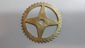
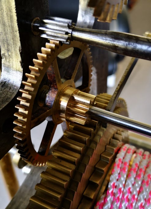
A client had a very old clock that had had a new barrel wheel made and fitted but the clock would not run for more than a few minutes.   There appeared to be an incompatibility either between the modulus of the new wheel and its mating pinion or the shape of the original pinion did not match the shape of the new wheel. 

If you spun the barrel wheel you could feel the resistance build up as the synchronisation between the two profiles drifted out.   Adding extra weight to the barrel helped but did not solve the problem.

So what to do ?   

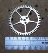
The barrel wheel was serious engineering and I did not fancy making a new one.   The existing mating pinion was a seven leaf format and its leaves were what you might call pear drop shaped rather than the expected profile.  The pinion arbor had a 72 tooth wheel driving the next part of the clock train but we did have a spare one of these to hand from the minute dial.

Calculations from the geometry of the barrel wheel resulted in a modulus        figure of 1.86.  A rather large value and not one that conventional cutters are readily available for.  The pinion was perhaps something that could be drawn in Fusion 360 and then made on my Tormach CNC PCNC440 milling machine.   The only snag was that the profile needed on the pinion would likely be weird and the world’s supply of brass could diminish rapidly while getting the profile correct.

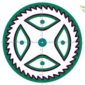
Using Gearwheel Designer I created what would be the expected profile for a 7 leaf pinion with a modulus of 1.86.  This was exported as a DXF line drawing into Fusion 360.  This outline was extruded in Fusion into a 3D design and a boss was added to mount the 72 tooth wheel. 

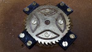
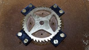
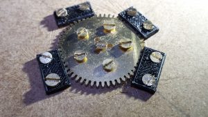
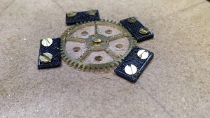
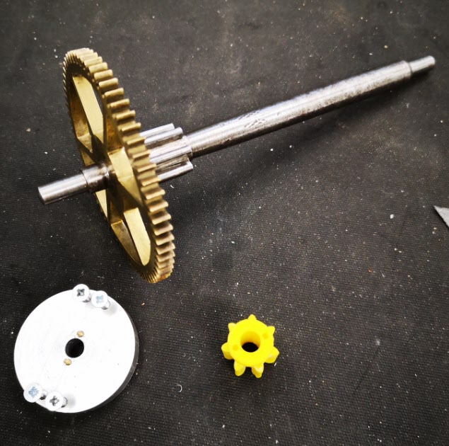
The design was 3D printed on my Sindoh 3DWOX printer and was mounted on a 6mm silver steel arbor.   I added a driving disc that interlocked with the printed pinion and the crossings on the wheel to drive the assembly.  Surprise surprise it didn’t run but it did mirror the regular pattern of stiffness of the original pinion. 

Original arbor , pinion and wheel with the driving disc and a test profile
The original arbor, pinion and wheel together with the driving disc and a 3D printed pinion test profile. The driving disc has screws to lock it to the wheel and two protruding pins to lock into the 3D printed pinion profile under test. The 3D printed profile was a tight pressure fit onto the new 6mm arbor.

I now had the test bed for quickly making and testing different pinion profiles. There followed a number of hours watching the engagement progression of the profile of the pinion into the barrel wheel and then trying to conceive a profile for the pinion that might run. 

3D printed test profiles
Various trial profiles and the temporary driving disc to engage with the 72 tooth wheel


Test pinion in place on the new arbor
A test pinion in place showing the 72 tooth wheel and the driving disc

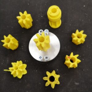
Fusion 360 made this process so easy and round 10 printed test profiles later I had success with a clock that now ran.    The driving weight on the barrel was around 11kg and it looked to be worthwhile wasting some brass making a ‘proper’ one. 

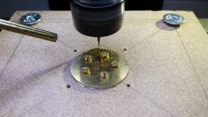
I took the 3D design and produced CAM code in Fusion.   This would cut the profile ‘on end’ using an adaptive first cut with a 4mm end mill followed by rest machining the remaining material with a 2mm end mill. 

Images of the Fusion 360 process of creating the new 7 leaf pinion
The Fusion 3D model of the pinion, the CAM simulation of the leaf cutting, first adaptive cut of the leaves and rest machining final pinion

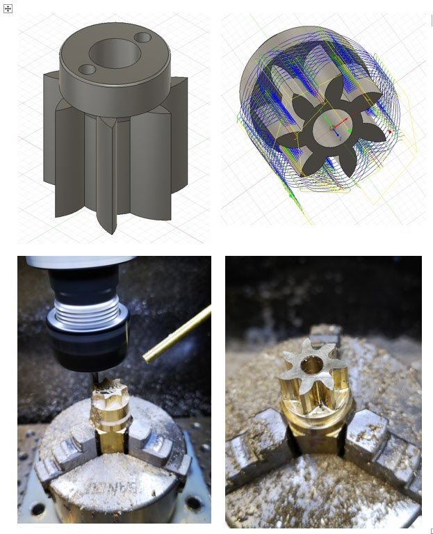
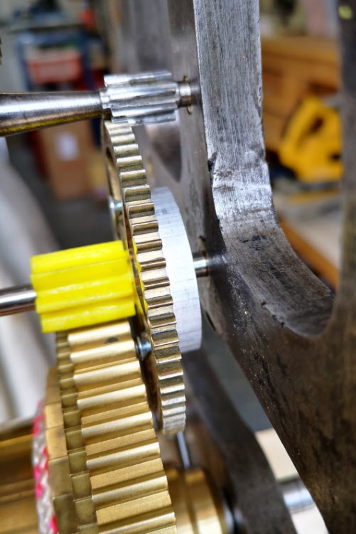
The resulting brass pinion was mounted on the arbor and the clock ran with a strong beat.   As expected the brass pinion gave less surface to surface resistance than the 3D printed part and the barrel driving weight was now able to be reduced down to 6.25kg.

new pinion mounted in the clock
The finished pinion mounted in the clock on the new arbor

I ran my Microset Timer on the clock overnight and had a first off timing error of 5 minutes per day which was fixable with a pendulum tweak. The movement had an instability of a few seconds per day which was quite astonishing.

The conclusion of the experience is that at first glance this seemed like a conventional pinion cutting exercise …. but M1.86 cutters are not readily available.   If a cutter could have been found at less than a King’s Ransom it is likely that the resulting conventional profile would have been wrong to match the barrel wheel.   

The alternative route that was taken of Gearwheel Designer to Fusion to 3D print to Fusion CAM to CNC machining solved the problem albeit with a final weird profile.    The purists and traditionalists will groan.   There will be a gnashing of teeth and a pulling out of hair. 

Does it really matter if the result is new life for what could have become a heap of scrap metal ?

Similar or related subjects : –

Clock Wheel Cutting Adaptation of a Tormach Saw Mandrel

I am slowly building up to being able to cut wheels on the Tormach PCNC440 with two possible methods.

The first is using Gearwheel Designer which is mentioned elsewhere on my blog.   

The second route is  more conventional using a PP Thornton or similar cycloidal tooth cutter and a dividing device on a rotary table.  This later method is how wheels are traditionally cut in a lathe and there is a lot of information available on this.

In order to use the cycloidal cutters I need some form of arbor to mount the cutter in the Tormach spindle.   I could simply turn a piece of steel bar to suit and mount this in a ER collet in the spindle.   The downside of this simple approach is that every time the arbor was fitted into a collet the cutter would be at a different height from the table.   I really wanted something a bit more repeatable as the centre line of the rotary table will always be the same so why not the cutter centering.

When I ordered the Tormach PCNC440 I also ordered the Tormach small rotary saw arbor (which to date I have never used).   Pondering this last night I sketched up an adapter in Fusion 360 to allow an involute cutter to be fastened to the end of the saw arbor.   

This is shown below. 
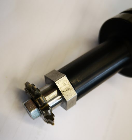
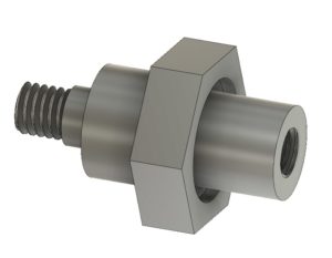
It is made from a piece of 19mm AF hexagonal steel bar with the hexagonal flats going to be used as a tightening it in place in the Tormach arbor. My Myford Super 7 when used with a 3 jaw self centering chuck is not bad on concentricity but for really accurate centering I swap the chuck for a collet face plate instead.    This job was going to need both.

First operation was to turn the hex bar end that would screw into the arbor.  This was done in the lathe chuck.   It was a simple turn to a diameter and drill and tap the end with M6 to match the arbor mounting.   The only pain was the arbor has a slightly protruding lip so I had to undercut the mounting face for this.   Rather than trying to be clever I did it by hand using a graver.

While the hex stock was still in the lathe I roughly turned down the other end of the adapter to the primary diameter and slightly oversize for the cycloidal cutter bore diameter and then cut off the stock so far.

It would be important to get the cutter mounting running as square as possible so I swapped the lathe chuck for the collet plate and mounted the arbor end of the adapter in the collet. I carefully turned the shoulder for the cycloidal cutter diameter and then reduced the remaining length ready to cut a M6 thread.

Here are a couple of images of the finished adapter.

Tormach TTS saw collet with my adapter and a typical clock wheel cutter
Assembled cutter on Tormach TTS collet

I am pleased to say the idea went almost to plan and it runs very true in the Tormach spindle.

I was a bit over enthusiastic with the graver but this is of no consequence.

With hindsight the shank between the cutter and the hex section ought to be longer as this will restrict the diameter of the wheel that can be cut before the blank catches the hex section peaks.

One step closer to trying this method. The next experiment is to work on a sub routine in GCode to move the cutter back and forth while cutting and with the ability to easily program the number of cuts.

Similar or related subjects : –

Some Particularly Sad News

Readers of my pages will be aware of my involvement with Graham at Delph in helping to further develop his Gearwheel Designer program.  It seems there is a ‘gentleman’, Mr di Claudio,  who appears to have stolen the design and hacked the code.  He appears quite proud of his pirating activity.  It is a sad reflection of the times and the industry.

Knowing as I do the amount of time Graham has been putting in on his code I would recommend anyone interested in his application to do the honourable thing and subscribe the relatively small amount requested.   Without people like Graham having the innovative thought to produce such applications our hobby and indeed commercial interests would be all the poorer.

Similar or related subjects : –

Ratchet Wheel Trial Cut using Gearwheel Designer

I am now running Version 21 of Gearwheel Designer and it gets better all the time.

I decided to make a ratchet wheel as my next test.  This highlighted the need to think about the process order on the mill.   Below is the design image in Gearwheel Designer.

My CNC sequence was as follows : –

  1. Cut the square brass blank a little oversize and draw a diagonals on it to show the nominal centre (Manual operation).
  2. Drill four holes in the corners outside of the working area of the cutting and use these holes to fasten down the blank to the milling table (which I had protected with a piece of MDF). (Manual operation)
  3. With a drill bit as appropriate, drill radial holes in the centre of the spoke petals and also the centre hole.
  4. Fasten the petals down to the MDF using these radial holes.
  5. Cut the gash outline of the wheel.
  6. Remove the four corner screws and remove the liberated brass outside the gash cut.
  7. Cut the rough pass on the teeth.
  8. Cut the fine cut on the teeth.
  9. Fasten down the periphery of the wheel with small clamps.
  10. Gash cut the spokes to leave the petals free from the blank.
  11. Remove the screws holding the petals and remove the brass liberated.
  12. Run the final cut on the spokes.
  13. Job done apart from a light sanding to remove any small burrs.

Some more images follow : –

Gash cut done and teeth cut twice round. The clamps are in place holding it down while the petals are cut.

Petals cut and removed for the final cut on the crossings

Finished wheel after a light papering

The purists will now tell me how it isn’t a proper wheel because the crossing interfaces to the rim have radius rather than a sharp corner.

Well a file will soon fix that …. and I can tell them how I watched another three episodes of House of Cards while this wheel was being cut.

Similar or related subjects : –

Delph Gearwheel Designer clock wheel design software

I came upon the Delph site and was excited at the possibility to cut clock wheels on the Tormach PCNC440 as this was one of my prime motivations for the purchase.   Does anyone love crossing out wheels ?

Delph has been feeding me with updates to their code and it is starting to make sense what it is doing and I like it.   Today I have run a wheel on slightly hybrid code (Delph plus my direct G Code hacks) and I am impressed so far.

The Delph code lets you design all manner of wheels for clock and other applications.  You can define the style of the teeth, the crossings etc and you can drill or mill arrays of holes.   You can also define the order of the machining processes.   I bolted down a square of brass with corner holes holding it down – you can see the holes in the MDF below.  Next I had the Tormach PCNC440 drill the three sets of holes in the blank, then cut the blank to circular size to match the teeth maximum diameter.  In the picture the mill is cutting a rough cut first pass on the teeth using a 0.7mm carbide cutter.   Next is the tooth fine second cut and then I can cut out the crossings which is what the five screws are for – holding down the petals that will become free once profiled.

It is all in 2.5 D but well worth a look.

http://www.delphelectronics.co.uk

Delphe GearWheel Designer Tormach
First wheel tooth being cut using the Delphe application.

Update : –

All went well in the first rough pass on the teeth called a Gash Cut in the software.   I was running at 4000 RPM and 5mm per minute and each tooth was taking 4 minutes with a slow 3mm lead in.  The second finishing pass was much quicker and now only leaves the crossing out to run.   As each petal of the crossing out is cut free , the screws shown above will keep the petal segments in place so there is no damage to the tooling.   I have made some small clamps on the 3D printer to put around the outside of the teeth to keep the wheel in place and centre screw to hold once the petals are cut free.

Gearwheel Designer, Tormach PCNC440, Fusion 360
Clamps in place ready to run crossing out

Crossing out completed and milling finished

Finished wheel after a light papering

What a feeling to complete it and thanks to Delph for their support in getting me there.

See some more details and screen shots here.

Similar or related subjects : –

Verified by ExactMetrics