Dry lining wall fastener fixing aid

In my experience there is only one fixing style that works with plasterboard lined walls. These are shown in the image below and are supplied in various mounting thread sizes. The image below shows the 4mm and 5mm versions. Also shown is an example of how they expand out when you clamp them inside the cavity behind the plasterboard. Note that while intended for dry lined walls, these can also be used on thin walled surface such as a modern ‘hollow’ door (good for bathroom towel hooks). The fasteners are available in various lengths to suit the mounting surface thickness.

In use you drill the appropriate clearance hole for the body (6.8mm for the 4mm version and 8.8mm for the 5mm version) and push the fastener into the hole so it is flush with the outer surface of the plasterboard. You tighten the screw to cause the ‘wings’ to expand in the cavity.

There are a few issues with this. To cause the expansion process to start you have to apply a lot of pressure downwards on the screw head. Once you feel the screw beginning to turn easier you are on the way to crushing the wings against the wall inside surface. The next test is judging when you have reached optimum expansion of the wings. This comes with experience. The screw rotation will go from relatively easy to increased pressure.

When used on plasterboard the two triangular prongs on the fastener are supposed to grab into the plasterboard surface and stop the fastener rotating as you tighten the screw to initiate the wing expansion. My experience is that you need to apply heavy downward pressure on the screw head to stop the prongs just rotating free and cutting a nice circular vee groove in the plasterboard surface. This is slightly less likely to happen if you are fitting one to a hardboard surface such as a hollow door as the hardboard will give greater resistance to the rotation.

This tightening process can be helped if you put a washer under the screw head with some grease. This eases the possibility of the whole fixing rotating.

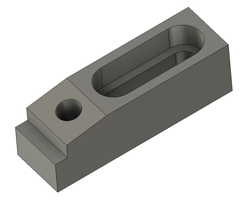
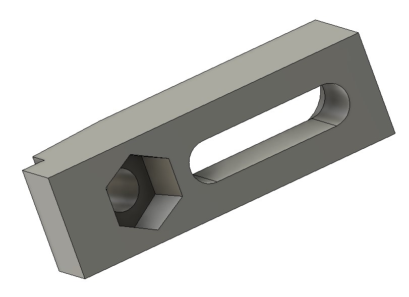
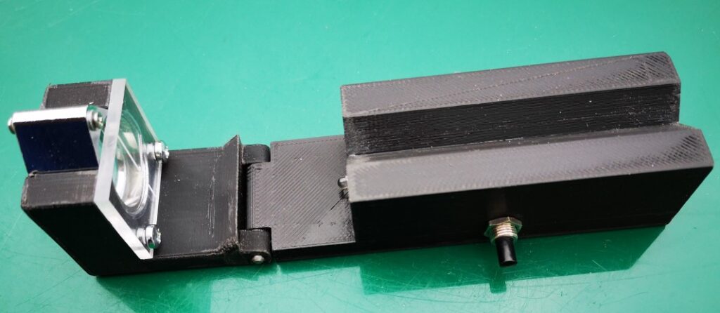
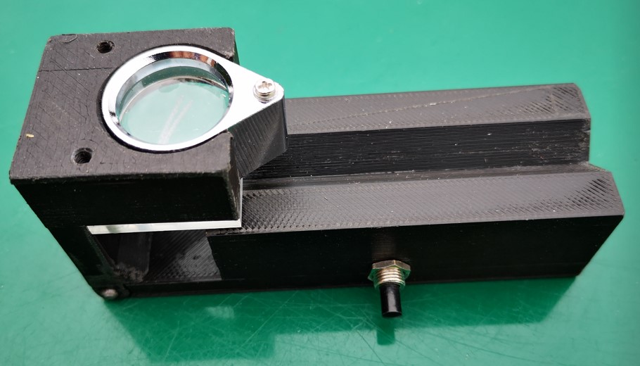
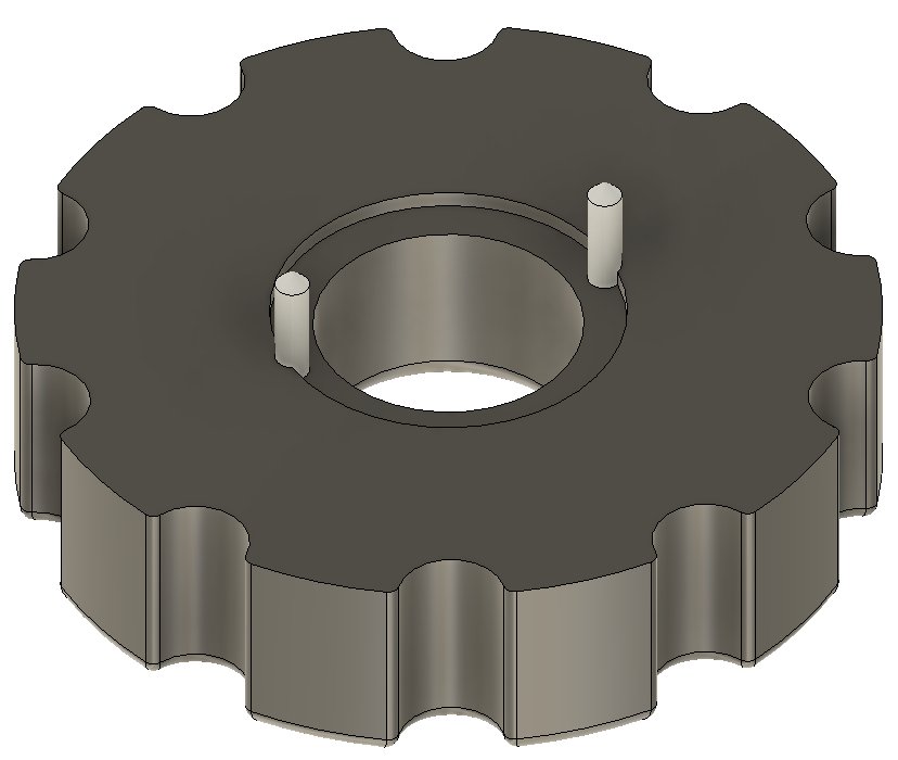
You can buy a tool for mounting these fixings. My version is a 3D printed double pronged restraining jig. So far I have created two sizes, one for 4mm and one for 5mm threads. It is simply a disc with two 1.6mm panel pins embedded in it that mate with the notches in the fitting. The tool is offered up over the fastener with the pins in the V grooves and then pushed home into the plasterboard. The pins embed deeper in the wall surface than the prongs on the fastener and stop it rotating.

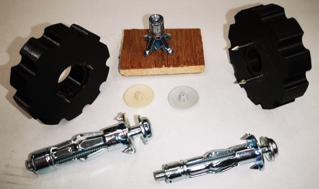
A couple of other comments. Once you have the fastening in place on the wall the screw thread will likely be longer than you will need to hold the object being fastened to the wall. You can therefore substitute a shorter screw as needed so long as it is long enough to mate with the fastener thread. You can also change the screw head style. When fitting curtain battens I use a number of these fittings along the batten length and replace the dome head screws with countersink heads into which I fix the commercially available small plastic star head covers (see below).

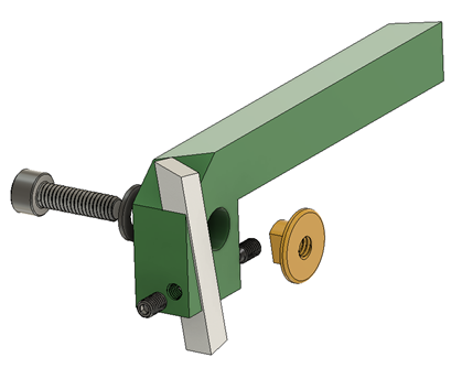
Here is an image of the fasteners, the two jigs sizes I use, a view from the rear of how a fastener expands in the cavity and the small coloured plastic covers that can be used to cover countersink screws.

Depending on the technique that has been used to fix the plasterboard, you can sometimes have a reduced depth of cavity for the fixing. This can be overcome by drilling the mounting hole for the fastening not just through the plasterboard but as deep as need to match the fixing’s length into the solid wall behind. This allows you to get the fastener in place and the expansion of the wings will not be inhibited. Clearly this is not so easy with a steel lintel behind the plasterboard …..

The STL files for the two sizes can be downloaded on the link below. I used PLA with a 4 perimeter print and 0.25mm layer depth. Once printed, clean out the two panel pin mounting holes with a 1.6mm drill. Cut the panel pins to around 6-8mm length and push home into the drilled holes. The small counterbore on the print surface will match the fastener flange but not to full depth so there is a pressure exerted from the jig as you push it against the wall.

Links to similar or related post are listed below : –

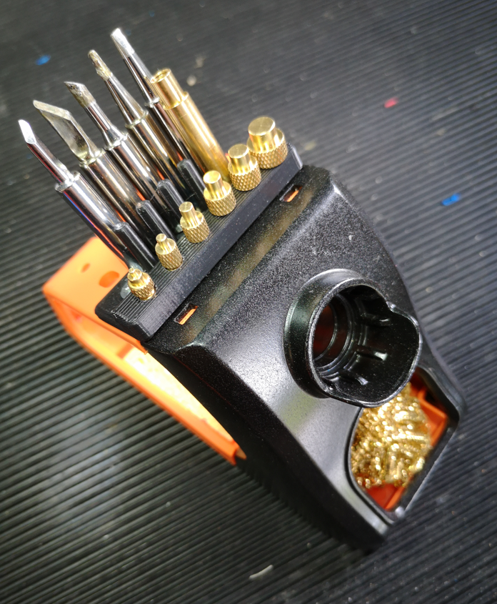
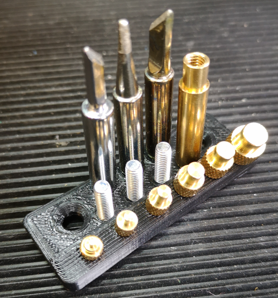
Soldering Iron bit storage on Lytool soldering station

Including a 3D insert tip holder

In my recent post on a 3D print insert stand I mentioned the use of the Lytool soldering iron station. This uses a Type 936 style soldering pencil and it is supplied with five different profile soldering tips. When using the iron for non insert related soldering, I have found it lightweight to use, very quick to get to temperature and generally a good alternative to my Weller TCP1.

After some research I found that the best match 3D inserts tips for the Type 936 pencil are a screw in set with a common mounting bit. Here is the Amazon link.

Having now got five different soldering tips, the insert holder and six 3D insert tips, things were getting a bit messy and a potential recipe for something getting lost with all the ensuing frustration. The solution was a simple holder for these various components that mounted on the Lytool soldering iron holder. Here is the Fusion image.

and here is the finished item mounted on the soldering iron holder.

Clearly as a 3D print you can’t go putting a hot tip on a plastic prong … but that aside it is functional. As an alternative you could replace the prongs with M4 screws. Here is a view of such a variant. This uses M4 x 15mm countersink screws but space is restricted on the rear side to allow for the screw head size. There is still room for seven standard tips. If the threads don’t print well then the screws could be fastened with nuts on the top side instead. This would also protect the body plastic from any residual heat in the tip.

Here is a ZIP file with the STL files for the two versions.

Links to similar or related post are listed below : –

Tangential Lathe Toolholder for Myford Super 7

Yet another design to add to the plethora out there

The concept of a tangential lathe tool holder had passed me by until Blondie Hacks mentioned it in one of her YouTube posts.  This resulted in an hour or more lost down an internet rabbit hole.   The conclusion seemed to be that I was very late to the party.  There are many designs out there which include the Eccentric Engineering commercial item.

I quite liked the look and simplicity of Mike Cox’s design. With the knowledge gained from my unintended meandering internet research, I tweaked it slightly and committed it to Fusion 360. This is shown in the pretty picture below.   Note my design was to be mounted in a QCTP on my Myford Super 7 and is intended to hold a 3/16” HSS tool. Here is my Fusion 360 image of the model.

The following ZIP file contains my full write up along with the Fusion 360 model for the toolholder and an associated 3D printed sharpening jig.

Update : This tool is very good. It can tolerate decent depths of cut and leaves a nice finish both turning and facing.

Links to similar or related post are listed below : –

3D Printed Mark Presling Clamping System

A PLA version of Preso’s versatile clamping system

Sometimes I think I am way out of touch when I suddenly find a new interesting YouTube maker site that had gone completely under my radar. Mark Presling is based in Australia and has some interesting projects and ideas on his YouTube vlog. My thanks go to Peter in Croatia for pointing me in Mark’s direction.

Mark’s latest post (Jan ’23) focussed on a work hold down clamping system using a variant of a ClickSpring eccentric screw and block concept. This looked quite interesting and was timely with my experiments with the Gack clamping idea.

I’m still in France, slightly idle but with Fusion 360 as ever close to hand. Mark’s post does not precisely detail the dimensions but I got a rough feel for proportions and modelled my interpretation of his clamp idea in Fusion. To give the eccentric screw clamp holding strength I embedded a M8 nut. The brass clamping block would remain the same as in Mark’s design and for clarity is not shown on the images below.

I sent some graphics and a STEP file off to Mark for his thoughts and we both agreed that a PLA or PETG version would work and probably be a simple low cost source for hold downs on many CNC router tables. Mark mentioned this in Part 2 of his video post.

Variants could be quickly made for different geometries to suit the work in progress. Like my Gack 3D print, the clamps would not stand up to serious full on metal CNC grunt milling but router table based profiling would be fine. The advantage a 3D printed clamp is that cutter dings when hitting the plastic would not do any damage to the tool. (I realise that none of us ever do that anyway ….).

In the ZIP file below there is a STEP and STL file of my interpretation of the clamp and also the Fusion 360 file for those wanting to play further.

I won’t be able to print the idea myself until I get home. I think it will need a vertical print to avoid the need for support material.

Links to similar or related post are listed below : –

Gadget Builder Drill Point Inspector

A 3D Printed Version of John Moran’s Drill Point Inspector

John Moran has an excellent website that details all manner of engineering projects. He is a keen advocate of four facet sharpening of drill bits and he details a Drill Point Inspector device for checking grinding results. I quite liked the concept and thought it would also be a useful asset for checking the condition of milling tools. The design uses a small inspection eyeglass magnifier lens that can be flipped from end view to side on view for tool tip inspection.

Those who know me through my blog will know that I am of a lazy disposition which tends to cause me to step back and look for an easy way to manufacture something. John’s design immediately suggested to me that a conversion to a 3D printed equivalent would be a practical solution. I also picked up on a comment that John made that you needed good light to be able to view the drill point clearly. As a result of this comment, the 3D design evolved with the addition of a simple LED illuminator. I also added a ‘right angle stop’ so that when hinged for side viewing, the lens was held more repeatably.

Because the inspector will only be used now and then, I opted for two small hearing aid batteries as the LED power supply together with a single resistor and switch. I printed two slots in the cavity for a pair of nickel silver battery contacts to sit in.

View into the battery and switch cavity. The battery contacts are bent pieces of nickel silver or tinplate

The design was modelled using Fusion 360. The two parts of the body were 3D printed. The Perspex viewing graticule was CNC milled to size and the reference comparison lines were also engraved on the CNC. The inspection lens is available from many sources on EBay (x30 21mm). The inspection screen mounting holes are 3D modelled. Here are a couple of shots of the finished model.

3D Model of John Moran's Drill Point Inspector showing the model flat for end viewing of the tool
Model hinged flat for end viewing of the tool (the LED is just visible)
3D Model of John Moran's Drill Point Inspector showing the model hinged at right angles for side viewing of the tool
Model hinged up for side viewing of the tool

Note that the addition of the LED illuminator needs the modelling of a cavity on the bottom surface of the main body. When printing this part it will be necessary to have the printer provide support structures. I also printed a cover for the cavity but this could be an offcut from an old credit card or similar thin plastic sheet.

Once printed I found the parts needed slight ‘fettling’ to remove any surface striations on the V block section, in and around the hinge section and around the eyeglass mounting slot. That aside it printed fine and the parts went together easily. More to the point it works well and is a useful tool to have to hand.

The Fusion 360 file and STEP files for the main two model parts are available in the following ZIP file. If you need additional information please get in touch.

Links to similar or related post are listed below : –

Verified by ExactMetrics