Arc and Circle I and J code calculator for GCode cutting paths

I & J Arc Code Calculator (with updated spreadsheet)

I had a need to hard code a circular PCB cut out CNC code that would cut four arcs around a milled PCB and leave four breakout tabs to retain the board in place in the blank until the job was finished.

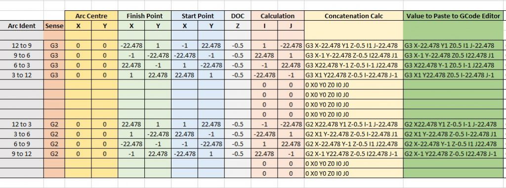
To create I & J codes you need to know the start point, end point and radius of the arc.   The end point becomes the X and Y.  The  delta X and Y location relative to the radius centre point X and Y becomes the I and J values.   You can also add a depth of cut value for Z as part of the block.  Note that the Arc is assumed to run anticlockwise when using a G3 code running from start point to finish point.   Use G2 if you want a clockwise motion.   The principle is the same with both rotations.

You end up with a block code of the format G3 (G2) Xa Yb Zc Id Je where a,b,c,d,e are the coordinate values.  I found that working with positive and negative values when trying to find the I and J values relative to the centre was hurting my brain.   A spreadsheet was needed …..

Screen shot of I and J calculator spreadsheet
Screen shot of I and J calculator spreadsheet for G2 and G3 coding with examples based on CW and ACW arcs around quarters of a circle with small gaps between each arc.


You can download the sheet as a ZIP file from the link below.

Arc and Circle Calculation Sheet for GCode

Similar or related subjects : –

How to Register Velux radio controlled windows

Velux Window Registration of Window to Controller

An Off Piste rant ….having just had a few hours of my life dribble through my fingers I thought others might want to avoid having the same misery.

We have two Velux centre hinge windows in our ‘Summer Room’.   They have been temperamental about behaving to the handheld controller over the years and at the weekend they both went AWOL to the controller while open.

The handbook is a bit disjointed and has a circular path if you have a problem that does not get you anywhere apart from very frustrated.

First thing is that if you end up with the window open and not responding there is a tiny white button on the electronics box inside of the window frame which if you press once will cause the window to close.  This assumes that the window has failed fully open and you can get at the button….

Now to the main problem, getting the remote control to ‘see’ and register the window(s).   I got the spectrum analyser out and checked what was happening.  When you take the batteries out of the controller and give it a hard bounce it takes you into a primary screen asking for the language option you want.   This is followed by a Register menu option.   When I selected this I could see a polling signal at 868MHz (European short range devices frequency allocation) so the controller looked to be working OK.

To activate the window to listen for a poll from the controller you have to switch off the power to the window and then switch back on.  For the next 10 minutes it should be listening for the controller polling request.

Well I followed all this but the controller was not seeing the windows to register them.  I could not see the ACK on the analyser coming back from the window so something was wrong.

Digging in the handbook there is mention of a ‘window reset’.   The same white button that allows you to close an open window also acts as a reset button for the window.   If the window is closed you can manually open it to get at this button. You hold the button down for 10 seconds and this causes the mechanism in the frame to cycle back and forth and make noises.

When all stopped and it went quiet I turned the windows off and on and re-tried the controller and immediately both windows registered.

Magic.   I can now get on with something more important or at least more interesting.

In summary : –

  • Remove the batteries from the remote controller.
  • Manually open the window and press the white button on the black electrical unit on the frame for ~8 secs. The white T shaped part of the mechanism will go into an ‘in and out’ process for 6 or more times and then stop.
  • Close the window manually and switch off the power to the window.
  • Put the batteries back in the controller.
  • Switch on the window.  You now have 10 minutes to register the window.
  • The controller will ask for the language to be selected and will then give an option to Register. Cross all your fingers, hold your breath and then press Register and wait for registration to happen.

Hope that helps someone lose a little less of their life trying to get this to work.

Similar or related subjects : –

Raised bed vegetable garden infrastructure details

Vegetable Garden Notes

This write up is a bit off piste to my usual engineering activities.  With present social distancing in place because of CoronaVirus and the resulting shortages of some fresh vegetable foods in the shops, it has never been a better time to grow your own.

Vegetable garden layout picture
Spring time view of the vegetable plot

For a number of years I have cultivated a veg plot and it is now quite mature.   Along the way it has become formalised and as a result it rolls along from year to year without really needing much thinking about.   The only problem in recent years is we are quite often in France when produce reaches peak availability.   Our house sitters therefore reap most of the benefit.

Read more in this pdf download

Similar or related subjects : –

Hall Effect Based Tool Height Setter for use with PathPilot

I had been using Hall Effect devices to modify my William Smith Gearless Gravity Arm clock and had been surprised by their ease of use and repeatable trip points.  (More about this to follow in a separate post).

I had also been frustrated with my inability to set tool heights reliably in PathPilot despite using various methods all of which didn’t want to agree with each other.

This resulted in the construction of a Hall Effect based Tool Height Setter that appears to solve the problem.   The write up is lengthy so I have committed it to PDF for download but here are a couple of images to give you an idea of the result.

sketch view of tool height setter concept
A simple cross section sketch of the tool height setter concept using a Hall Effect sensor

 image of finished tool height setter using a Hall Effect sensor

Finished tool height sensor mounted on the PCNC440 milling table

Link to Tool Height Setter write up

Similar or related subjects : –

Micro USB with 5 core cable

Lots of activity to be documented and posted but let’s start off with a short note.  Not earth shattering but might help someone somewhere.

I had the bright idea of using Micro USBs as a connecting medium on a couple of projects.  This was driven by the need for a 5 wire connection.   The design was finished and I dug out the Micro USB to Micro USB cable that had been bought in for the project and connected things together.   All the LEDs went out on my project circuit board.  Gloom.

After buzzing the cable through I found that on a standard Micro USB cable the Sense pin is linked to the Ground pin.   There are not 5 independent and isolated cores as you would expect.  Just four. What to do ?

By chance I had some Micro USB connector ends with solder tabs but no shells.   I did not have any flexible small diameter cable with 5 cores.  After some discussions with my other half she offered to plait 5 independent cables together for me as a cable form.   These were soldered to the Micro USB ends.  Two small end caps were quickly designed in Fusion 360 and took 10 minutes to print on the 3D printer. Job complete and project back up and running.

custom micro usb with 5 core cable
Custom Micro USB 5 core cable components showing solder terminal end connectors, 3D printed shell and plaited 5 core cable courtesy of my wife.

Similar or related subjects : –

Verified by ExactMetrics