Some head scratching but a working solution
I had a request for help with a CCTV system where the owner wanted to add a remote camera to an outbuilding with no cable route possible. This should have been a JSN job (Just Say No) but I’m always up for a (steep learning curve) challenge. After some investigation (back of a napkin sketch and a quick Google search) I opted for a 5GHz WiFi bridge and thought the job was going to be easy. JSN jobs are like that but you have to be conscious that they come configured with inbuilt mission creep.
The WiFi link was a 24V power over ethernet (PoE) system. The existing three cameras were 48V PoE and the additional camera was to be the same.
Here is the final configuration. The red lines are PoE and the blue lines are just basic CAT5 unpowered connections.
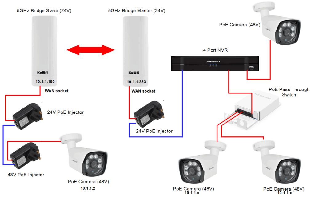
The NVR is a SPRO four port device with 48V PoE on all ports. To save cabling the owner had used a PoE pass through switch so two cameras could share the same cable running back to the NVR. The existing third camera was a direct feed from the NVR. I was quite impressed with the pass through device. It has the capacity to allow four cameras to share the same PoE NVR connection.
Back to the plot … Adding the fourth remote camera using a bridge would have been simple if the bridge was 48V PoE powered but it was 24V PoE. The remote location therefore needed two PoE inserters – a 24V one for the bridge and 48V for the camera. The LAN ports on the two inserters just need connecting together to complete the link. The NVR ‘sees’ the remote location as a locally connected camera.
Something to note. The bridge (KuWfi) as delivered has two IP addresses configured, 10.1.1.253 for the Master location and 10.1.1.100 for the Slave location. All the cameras are allocated 10.1.1.x IP addresses on the NVR. The NVR also has an internet connection for remote Smartphone viewing.
KuWfi provide an application to configure the two bridge units. I spent a long time trying to work out how to get this to respond to either device. In the end a light bulb moment reminded me that a previous Chinese sourced product had the same issues. I had traced this to a Chrome related problem (which I never solved) and found the Application would only work using Edge. The same happened this time. Using Edge got me into both units without a problem. Note that you have to set your host interrogating computer to be on the 10.1.1.x domain.
There is a signal strength graphic on the Slave GUI which is very useful. You can connect your computer LAN port to either the Master or Slave 24V injector LAN port and request either of the two addresses (10.1.1.100 or 10.1.1.253) from either end of the link
Just think how much simpler it would have been if the bridge also ran from 48V …. maybe someone produces a 48V to 24V PoE step down converter ? Or maybe I should just stick to the things that I pretend to know more about … and JSN.
Links to similar or related post are listed below : –