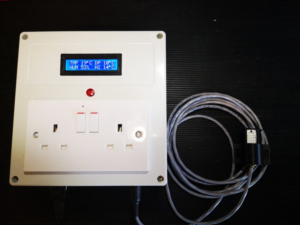
Dewpoint Monitor Updated Arduino Code

Dewpoint Monitor Auto Reboot facility added

In November 2021 I detailed a Dew Point Monitor. This was aimed for workshop use so a heater or dehumidifier could be turned on automatically to help prevent rusting of assets.

This has been very successful but had one minor issue. If the sensor failed or became disconnected the Arduino would lock up on sensing the problem. Plugging the sensor back in would not re-boot the code. I have added an auto reboot on sensor fail detection.

I have also removed the code that flashed the display after a humidity detection as this seemed superfluous.

The revised write up which contains the code listing is attached on the following link :-

Links to similar or related post are listed below : –

Technoline Wireless Weather Station problem

WS-2350 Poor Battery Life

I have had my WS-2350 Weather Station for a very long time and it has always worked reliably. The batteries recently died in the base station unit (3 x AA) and I replaced them. The unit sits in the kitchen and on entering the kitchen the following evening I noticed a glow coming from the LCD screen backlight LEDs. This was unusual as the LEDs should switch off after a few seconds of a key press. I didn’t think anymore about it and went to bed. Next morning the low battery symbol was showing…. and the LEDs were still dimly showing light.

I took the unit through to the workshop and powered it from a 6V external supply. Sure enough the LEDs were on and the current drawn was around 40mA, far too high for long life battery operation.

I removed the eight screws holding the case rear in place and struggled to remove it. There was a build up of corrosion around the battery contacts making them tight in the back cover moulding slots. Some careful cleaning eventually cleared this and the back cover came off. This revealed more accumulated ‘fur’ corrosion around the PCB lands holding the battery contacts and elsewhere on the board. This was cleaned off but the current drawn still remained high.

I next removed the PCB from inside the case. This needs six screws to be removed. A word of warning. These six screws while holding the board in place are also responsible for applying pressure to the conductive rubber contact strips that connect the LCD screen to the PCB. Be very careful not to disturb these strips. The board is also connected to the VLF rod antenna that receives the off air time code updates and also to the antenna for the radio transceiver that connects to the outdoor sensor module. Be very careful not to disturb these components.

I gently lifted the PCB out and sure enough there was even more corrosive fur on the back side of the PCB around the battery terminals and elsewhere on the board. I thoroughly cleaned all this off and with an abrasive pencil brightened up the the battery contacts.

After fastening the PCB back into the case, I powered it back up from the external supply. To my relief the LCD had re-connected okay and was fully working. More important was the power consumption had dropped to microamps. Problem solved. The corrosion somewhere on the board must have been creating a partial short across the PCB tracks. This must have been sufficient to make the processor think a key was still pressed and therefore the backlight LEDs needed to be held on.

As I had never had leaking batteries in the unit I would guess that there had been soldering flux left on the board when it was assembled and this had absorbed moisture and had ‘grown’ and become conductive over time.

I hope this helps someone who might be having similar problems. When battery powered devices are running with very low current it does not need much contamination between copper tracks to cause all sorts of weird effects.

Links to similar or related post are listed below : –
Replacement Whistle on Polly V Steam Engine

Spluttering Banished to be replaced by a Banshee

It had become a standing family joke on steaming outings that my Polly V whistle left a lot to be desired.   Quite often it would do nothing more than a feeble splutter.   The Polly V kit supplied whistle is fitted under the running board on the left hand side of the cab.   The pipe run is long and somewhat tortuous.   I had insulated the pipe to reduce feed loss but this made little difference.   The whistle valve also had a gentle leak and was very stiff to activate.   All in all not a good setup.

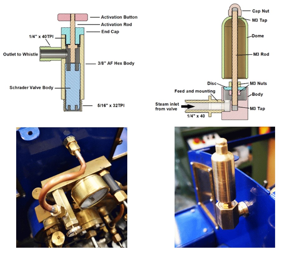
A recent article in Engineering In Miniature (EIM) by Richard Wightman (September 2022) went into detail about a whistle and valve combination he had created.   The whistle was fairly conventional but very compact.   The steam control valve was unusual in that he used a standard tyre Schrader valve.   This tweaked my interest and I set about upgrading my Polly V locomotive using this technique. Here are some Fusion 360 images and shots of the new valve and whistle mounted in place on my Polly V.

Here is a blow by blow description of the process as a PDF download.

Links to similar or related post are listed below : –

Noga Tool Christmas Present

Every workshop should have one

There was a recent thread on the MEW forum about Noga tools. It led me to download the Noga catalogue as a PDF. I am amazed at the technology that Noga produce to just remove burrs.

They are lovely tools and well worth the investment. I particularly like the external Rotodrive EX18 countersink. This is very handy for cleaning up the end of a newly threaded rod so the new thread will ‘take’. So quick and easy.

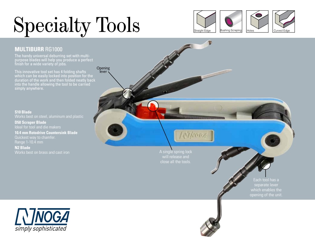
What really took my fancy in the catalogue on page 51 was this combination tool. That’s certainly one for my Christmas list.

No affiliation to Noga. I just like their technology.

“Better to have it and not need need it than to need it and not have it” – Jimmy Diresta.

Links to similar or related post are listed below : –

Edge Technology Lathe Tool Setter

A useful tool for setting lathe tools on centre

There are many ways to set a tool centre line on a lathe. The most basic is just to trap a 6″ rule between the workpiece and the tool edge and adjust so the rule is vertical.

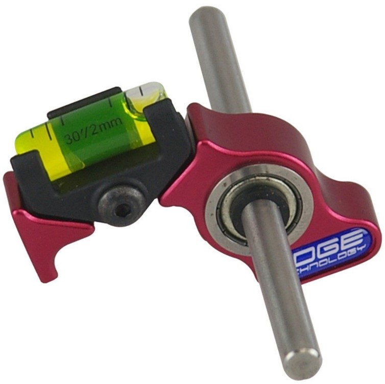
One gizmo I picked up at a trade show from the Machine DRO booth is this very useful tool by Edge Technology.

Edge Technology Lathe Tool Alignment jig

It is simple but clever. You mount the rod in the lathe chuck and then rest the bubble anvil on the tool edge. Edge Technology also do a more refined version with a calibrated scale.

It is not something that you use every day but every now and then I have a session with it and go through all my QCTP tooling and tweak them.

(If it has been one of those ‘not settling to anything’ days you can at least switch the workshop lights off with a warm glow that you did something useful …)

In the UK they are marketed by Machine DRO

(I have no affiliation to Machine DRO or any other manufacturer or supplier I might mention in my write ups but I will mention any nice pieces of kit I come across or use).

Links to similar or related post are listed below : –
Verified by ExactMetrics