Arduino Processor Reference Clock Accuracy

Of late I have been going round in circles on a project to keep our local church clock roughly on time. I say roughly as my idea of timekeeping does not accord with the aspirations of the village residents. Quote ‘ I only need to know when it is the time to go inside for a brew’ / ‘knock off for the day’ / ‘get my skates on or I will be late for work’ etc. I was thinking sub seconds and they were thinking a minute or so as being perfectly adequate. The exception is at 11am on the 11th of November when it has to be exact.

That as it may be, the project is moving along. The first problem was what to measure on the clock to reference the time adjustment. The pendulum (1.25s rate) is clearly the easiest choice and a sensor beam being broken by the pendulum swing will solve this problem. The slight problem is that the sensor will not necessarily ‘switch’ at the same time when being approached from the two directions of the pendulum swing. My Arduino skills might struggle to come up with some code to discriminate this so I reverted to simple CMOS logic. An ICM7555 acts as a monostable that has a period greater than one swing. This is triggered by the falling edge of the swing pulse derived from a simple differentiator network. The monostable extended period pulse is then gated with the incoming pulse using a CD4001 Quad NOR to always give me half the pulse rate regardless of the swing direction. That probably makes no sense at all so here is my back of an envelope waveform diagram and circuitry.

The circuit has turned out quite useful for other applications. I also refined it to have a CD4024 ripple counter fed from the output at E. This allowed extended logging periods to be achieved. I also utilised the unused gates on the CD4001 to provide an isolating buffer on the input signal. This meant the differentiating network would always see the same drive signal regardless of the incoming waveform and its source impedance.

Progress indeed. I now had a pulse train representing the clock beat period. All I had to do was measure the time taken between pulses and I could compare and adjust the pendulum rate.

Having got a reliable 2.5s pulse it was time to reverted to an Ardiuno UNO to measure the period. With some help from a friend we ran a sketch using millis to record the time between pulses. This minimalist sketch did not seem all that repeatable. I also did some tests with Frequency.h sketch code from the PJRC website (very useful source) and had similar poor results. I was using a FY6900 as my reference 1.25Hz signal and to get a 1.25Hz reading I had to offset the FY6900 quite a way from nominal. What to believe?

In a bid to get a known good reference I powered up my Arduino GTU-7 GPS module and measured the 1 second output pulse using both of the above sketches and the results were not much closer to the truth. I tried an Arduino MEGA instead of the UNO and got a different set of inaccurate results

This led me to think that the UNO and the MEGA must be the cause. Looking at these two boards, both have a 16MHz crystal which I (foolishly) believed was the processor reference and therefore could not be that much off frequency. Totally wrong. The crystal is for the USB interface, not the processor. Instead the processor has a basic 16MHz resonator – not a crystal. I got out the magnifying glass and discovered this piece of surface mounted wizardry. Low and behold if I put my finger on the resonator to warm it up, off it went into dodgy stability land. It was pretty awful. I could make my readings whatever I wanted them to be just by timing how long my finger was in contact with the surface mount resonator package. Chocolate fire guard indeed.

What to do ?

I downloaded the ATmega258P datasheet and found that I could replace the resonator with a crystal. This looked complicated with references to fusible links and reprogramming of the processor all of which made me twitch. The processor had been running on a wobbly 16MHz source so why not a less wobbly one?

Rather than hack the UNO board, I eased the processor out of its socket and bent pins 8 (ground),9 (xtal) and 10 (xtal) out horizontally and plugged the processor back into its socket. Using a three pin socket pushed onto the pins as a mounting, I assembled the crystal across pins 9 and 10 and two shunt capacitors (approx 33pF) to the ground pin. The crystal came from RS Components (#8149440) and was a 30ppm spec. This socket mounted lash up was then pushed into place on the floating process legs – very healthy, no damage done to the processor or the board. Here is the ugly mess.

Switched on. It worked.

Suddenly all my test source readings took on a very stable repeatability and the readings were very close to what I expected. The GPS referenced 1s pulse was reading 0.999936 and my SY9600 was reading 0.999958. It looked like my new crystal reference must be slightly off frequency but a tweak of the shunt capacitor values will fix this. I think the SY9600 has a 10MHz TCXO so it should be good but I think I tend to believe the GPS pulse as being more accurately delivering a 1Hz rate.

The experts will tell me I should be adjusting the fusible links but I am inclined to stick with what I have got, it is working.

The result is I now have an ability to measure the pendulum rate and from this I can derive an advance and retard flag.

I am currently designing the front end circuitry as shown above into a PCB ‘shield’ to plug into the UNO. This will take the sensor input and give a slow or fast command pin output. More on this and general progress to follow.

Update (30/9/2024)

I changed the two crystal oscillator shunt capacitors to be a 22pFSMD in parallel with 1p8 caps when using the RS crystal as mentioned. Below is a suitable layout for the crystal and shunt caps. There are positions for two caps on each leg of the crystal. 15pF in parallel with 6.8pF would also work. I checked the frequency was close using a GPS derived 1pps signal feeding pin 8 on the UNO while running the frequency.h demo sketch.

The board can be connected using the mounting holes or it can be cropped and the residual pcb tracks used as direct connections using pins 10 and 9 both of which are bent out from the IC body. Pin 8 was left plugged into the IC socket and bridged and soldered across with a wire clipping to the crystal board. The crystal mounts on the rear. The board is so simple you could mill it on single sided copper clad with a burr in a Dremel.

The picture below shows the first milled version in place on the UNO. The layout above is a later tweaked version to better match the pcb pads to pins 9 and 10.

Links to similar or related post are listed below : –

Dewpoint alarm monitor to help avoid rust issues in the workshop

A Dewpoint Monitor to protect the workshop
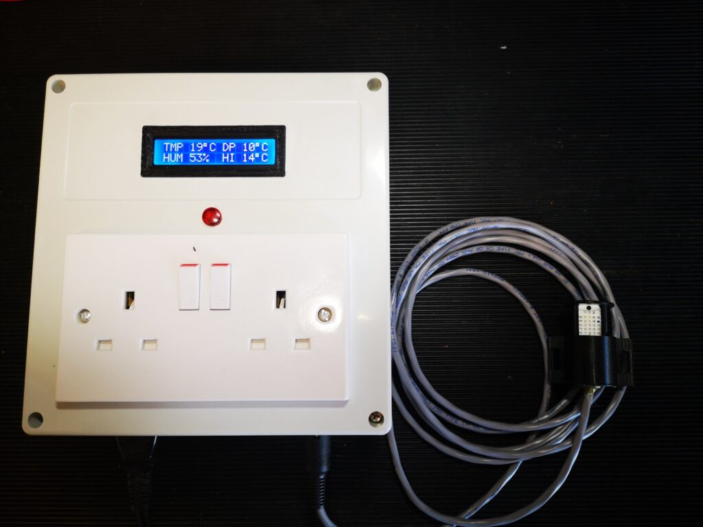
I have recently read a number of posts on workshop forums about rust degrading workshop assets.   When the temperature of the air reaches close to the dew point then the moisture in the air will condense on the cold surfaces in the workshop and moisture will inevitably lead to rust forming.

You can protect against this to some extent by ensuring that all exposed surfaces are coated with lubricant of some sort such as WD40 and only dry sources of heat are used in the workshop.   A better protection solution which was popularised by the clockmaker William Smith, is make a 50/50 mix of linseed oil and thinners and coat this on the objects needing protection.  This works well but does not last forever.

Looking around on the internet there are various Arduino projects to create a dewpoint monitor using the DTH11/DTH22 which are combined temperature and moisture probes.  Such devices, with a little bit of maths, can provide an alarm output if the dewpoint reaches close to the air temperature.   This could be used to turn on a heater and raise the air temperature and avoid moisture being deposited.  I opted to have the sensor remote via a cabled connection.

The dew point calculation I used is the Magnus-Tetens formula (Sonntag90).  This provides accurate results (with an uncertainty of 0.35°C) for temperatures ranging from -45°C to 60°C.

The dew point is calculated according to the following formula:

Ts = (bα(T,RH)) / (a – α(T,RH))

where:

Ts is the dew point;
T is the temperature;
RH is the relative humidity of the air;
a and b are coefficients.

The Sonntag90 constant values are : – –

a = 17.62 and b = 243.12°C;

and this is the final formula needed : –

α(T,RH) = ln(RH/100) + aT/(b+T).

I made a prototype using an Arduino Pro Mini as the controller and I used the above equation to calculate the dewpoint from the humidity and temperature readings input to the Arduino from the DTH22 sensor.   Once the dewpoint reaches within a defined limit of the temperature, a relay is closed to allow heaters to be turned on.   This trip point also causes the LCD display flash to warn that a trip point has been reached.

The working circuit was drawn in Fusion Electrical and a printed circuit board layout was created.   Fusion’s Electrical CAM output as Gerber and Epsilon files were converted in FlatCAM to CNC GCode.  The CNC files were than posted to my Tormach PCNC440 to mill the copper traces.

I designed the PCB using through hole components to make assembly easier for my more mature eyesight.

The trigger output from the PCB can feed any 5V coil relay that is rated with contacts capable of feeding the AC voltage and current needed for the heaters.

UPDATE 18/12/2021

Due to demand I have ordered a small quantity of offshore manufactured PCBs for the Dewpoint Monitor.  If you are interested in one then send me an email as per address below.  First come first serve.

UPDATE 1/11/2022

Auto reset code added should the sensor lose connectivity,

New write up is below including the new code

Similar or related subjects : –


Using Seeeduino XIAO and TFT SPI ST7735 display

A New Miniature Arduino Module

I should make it clear that I am not an Arduino expert so read on at your peril or your amusement.

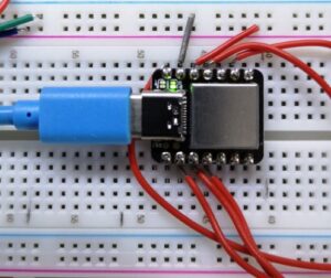
Myself and a colleague ‘play’ with Arduino devices.   We were impressed by the new tiny module from  Seeeduino called the XIAO.   It has just 14 pins, all of which double or triple up in their use.   See DroneBots blog for more info on the device’s capability.

seeeduino xiao miniature arduino module
The Seeeduino XIAO miniature Arduino module. The connector is a USB-C.

We had some SPI driven ST7735 displays from Adafruit which we had successfully used on conventional Arduino devices.  We wondered if we could drive them from the XIAO.   This resulted in many many hours of frustration.   The SPI bus uses 5 connections and two of these pins (SCK and MOSI) on a normal Arduino device are hardware defined ports with specific pin numbers.  These pin numbers did not match the hardware defined ports on the XIAO and it seemed as a result that it did not want to talk.

Many hours later we seem to have got a solution.   To save others having the same frustration here is the header information we ending up using that brought success.  This is followed by the connections from the XIAO to the display. 

#include <Adafruit_GFX.h> // Include core graphics library
#include <Adafruit_ST7735.h> // Include Adafruit_ST7735 library to drive the display
#include <SPI.h> //Include SPI control library

//Define pins :
static const int TFT_CS = 3;
static const int TFT_RST = 2;
static const int TFT_DC = 1;

// Create display:
Adafruit_ST7735 tft = Adafruit_ST7735(TFT_CS, TFT_DC, TFT_RST);
0    -    nc
1    -    DC  (to display pin 4)
2    -    RST (to display pin 3)
3    -    CS (to display pin 6)
4    -    nc
6    -    nc
7    -    nc
8    -    SCK (to display pin 8)
9    -    nc
10   -    MOSI (to display pin 7)
11   -    3V3 output (to display LITE (pin 10)
12   -    GND (to display pin 1)
13   -    5V output (to display power (pin 2)

I believe by using static const int the pins are locked against any further occurrences of these labels downstream in the code.   What isn’t clear is how the SPI protocol knows that the hardware pin numbers for MISO and SCK are not the usual hardware pins as per other Arduino devices.

Similar or related subjects : –

Adding stepper motors to a Myford VMB manual milling machine

Myford VMB Manual Mill Conversion to Stepper Motor control

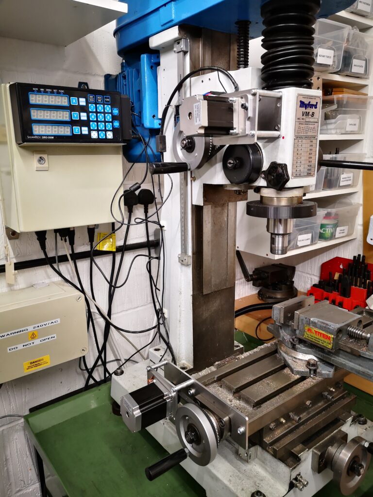
After many years of winding the Z axis up and down on my Myford VMB I have finally got around to fitting motor control and it is a joy to use.   I am however suffering from muscle wastage as a result.

stepper motor control of a VMB manual milling machine
A general view of the stepper motor control conversion of a VMB manual milling machine. Only the X and Z axis are completed so far. The control box is on the wall behind the mill and has the Shumatech DRO control panel mounted on the front panel.

I have done a write up for those who might want to also enjoy a less taxing movement of X, Y or Z axis on their manual milling machine.  Click on the link below to download as a pdf.

 Fitting XYZ motor feeds to Myford VMB v4

Similar or related subjects : –

Activity Update – FlatCAM, Arduino and Social Distancing

While I have been quiet for the last month or so there has been some intensive work by Dave and myself on FlatCAM.   We are in the throes of doing a formal document to help others get to grips with the process and techniques for milling circuit boards.

I need to also put my hand up and admit going over to yet another dark side by experimenting with Arduino technology.  This came about as a follow on to the work on silencing my Bill Smith Gravity Arm Gearless Clock.   With the help of another colleague we have replaced the discrete timer logic board with an Arduino.  I have learned quite a bit in the process and more details will follow.

Finally like many others round the world, myself and my wife are socially distancing ourselves at the moment but every cloud has a silver lining and this does mean I am spending even more time in the workshop doing ‘stuff’.   It has also been a good time to look at the workshop and make plans to tidy, organise and structure things better.  Some of the accumulated odds and ends are getting sifted and sorted and binned as appropriate.

Similar or related subjects : –

Verified by ExactMetrics