Adding Colour Coding to Fusion 360 Assemblies

How did I not know about this Fusion 360 facility ?

I was watching a YouTube video on Fusion 360 joints by Garin Gardiner. I couldn’t help but notice that he had colours on his assembly listing and time line. My interest was really perked…..

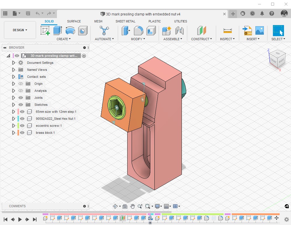
A quick search revealed that this is a standard but maybe not so obvious Fusion 360 feature. Go to the Inspect drop down menu and then Display Component Colours. Magic (albeit it can be a bit garish ..) but it really helps you to see what part or function is with what. If you start to feel a bit nauseous you just have to use Shift+N to toggle it ON and OFF.

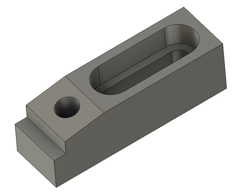
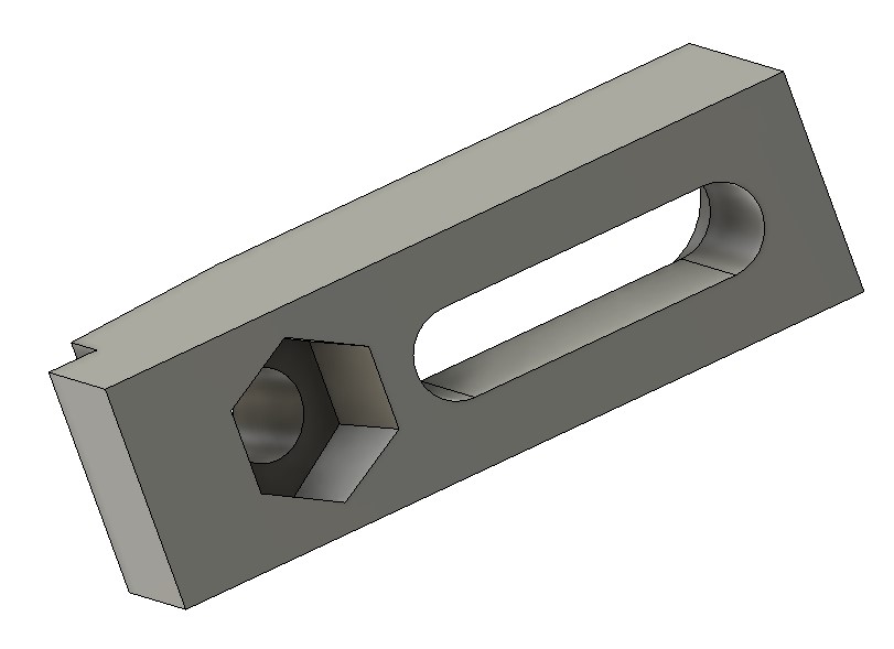
Here is my recent Mark Presling clamp in Technicolor. (OK the colours could be better chosen ..).

It’s funny how sad engineers get all excited about such simple things……

Links to similar or related post are listed below : –

3D Printed Mark Presling Clamping System

A PLA version of Preso’s versatile clamping system

Sometimes I think I am way out of touch when I suddenly find a new interesting YouTube maker site that had gone completely under my radar. Mark Presling is based in Australia and has some interesting projects and ideas on his YouTube vlog. My thanks go to Peter in Croatia for pointing me in Mark’s direction.

Mark’s latest post (Jan ’23) focussed on a work hold down clamping system using a variant of a ClickSpring eccentric screw and block concept. This looked quite interesting and was timely with my experiments with the Gack clamping idea.

I’m still in France, slightly idle but with Fusion 360 as ever close to hand. Mark’s post does not precisely detail the dimensions but I got a rough feel for proportions and modelled my interpretation of his clamp idea in Fusion. To give the eccentric screw clamp holding strength I embedded a M8 nut. The brass clamping block would remain the same as in Mark’s design and for clarity is not shown on the images below.

I sent some graphics and a STEP file off to Mark for his thoughts and we both agreed that a PLA or PETG version would work and probably be a simple low cost source for hold downs on many CNC router tables. Mark mentioned this in Part 2 of his video post.

Variants could be quickly made for different geometries to suit the work in progress. Like my Gack 3D print, the clamps would not stand up to serious full on metal CNC grunt milling but router table based profiling would be fine. The advantage a 3D printed clamp is that cutter dings when hitting the plastic would not do any damage to the tool. (I realise that none of us ever do that anyway ….).

In the ZIP file below there is a STEP and STL file of my interpretation of the clamp and also the Fusion 360 file for those wanting to play further.

I won’t be able to print the idea myself until I get home. I think it will need a vertical print to avoid the need for support material.

Links to similar or related post are listed below : –

Arduino ESP32 Feather Huzzah Installation

Installation was not as easy as expected

We are currently in France and this is always a time to relax away from the workshop and instead I usually end up doing computing ‘stuff’ which can be Fusion 360 designs or Arduino code. I have a couple of projects that will potentially involve either an Internet of Things (IoT) connection or possibly a direct WiFi connection between two Arduino modules.

I need to clearly state at this point that I am not a ‘softie’ and my Arduino code is a mix of Cut and Paste with some finger in the air suck it and see code. I get there in the end but it can be painful to be aware of hours of your life dribbling through your fingers all because of a forgotten curly whirly bracket somewhere in the code.

Back to the story. I got sucked in by the MKR1400 GSM as being a potential solution and signed up for an Arduino SIM to accompany it. This worked to a degree but then I discovered that the GPRS service is slowly disappearing all over the world as the spectrum is ‘repurposed’ for newer technology. The Arduino 33 IoT was then ordered and this seemed to work well with control over the WiFi network and from the associated Arduino mobile app. It did have some limitations for the main application I had in mind.

Next the ESP32 came to my attention. This is a fairly new kid on the block and has some very interesting facilities. The ESP32 Feather Huzzah version from Adafruit is rather nice as it has a Lipo battery connector. Unlike some other ESP32s it does not have a Load switch but just a Reset one. The ESP32 looked like the most attractive and a couple were ordered.

For those following in my footsteps you need to be aware of two things, First of all you have to download the libraries for the WROOM device.

https://raw.githubusercontent.com/espressif/arduino-esp32/gh-pages/package_esp32_index.json

You would expect that would be all but not quite. On Win10 you need to also download a new virtual USB driver from Silicon Labs CP210x and run “silabser.inf” from the ZIP download.

https://www.silabs.com/developers/usb-to-uart-bridge-vcp-drivers?tab=downloads

Once you have downloaded and run these you should be able to select and connect to the Adafruit ESP32 Feather in the Arduino device listing. (NOT the Adafruit Feather Huzzah ESP8266 from the board listing, it is easy to just ‘see’ the Feather Huzzah words,,, been there ….). You might also need to look in the Windows Device Manager to see which COM port has been allocated to the Silicon Labs CP210x driver. This will likely be a high number – COM9 on my machine. The IDE does not necessarily immediately ‘see’ this.

If the ESP32 appears to connect OK try uploading Blink. If all is well this should work. Beware it leaves the confusing last message on IDE 2.0 “Leaving … Hard resetting via RTS pin …” which looks like it is held but in fact it has finished and all is good.

Note that all of this waffle was written in January 2023 and the ESP32 hardware and support code etc is changing all the time.

In closing I can recommend DroneBot as a good source of Arduino stimulation.

Links to similar or related post are listed below : –

Updated Qidi i-fast driver for Simplify3D v5

Great Support from Qidi

Simplify3D has just released version 5 of their 3D printing slicer program. Simplify3D is a subscription program and is unlike Cura and Prusa which are both free. There is a special price for the upgrade if you are updating to the new version. I had been running the previous version of S3D and fully expected to be able to upgrade and use the same driver file (.fff) for my Qidi i-fast. Not so …. despite S3D saying my printer was compatible etc etc.

I sent a message to Qidi support and next day had a reply giving details of edits to the start and finish GCode routines. They also sent me a new .fff file that had been issued by S3D so clearly others had contact S3D with the the same problem. To be clear I am not saying S3D are not responsive. I just expected that they would check out these issues before issuing a major upgrade. Five Stars to Qidi though who as always are red hot on support.

Attached below the upgrade details as received in a ZIP file. Note that I am currently travelling so I have not had chance to check out the changes …. proceed with caution !

Links to similar or related post are listed below : –

Gack Vice as a 3D Print

A possible light duty clamping solution

I came across the design of a Gack machine vice on a metalworking forum.   This is a two part vice that picks up on the tee slots in a mill table to allow an infinitely variable clamping width within the limits of the table dimensions.   It is ideal if a part needs to be skimmed flat over a wide area.   The item to be machined is clamped by an adjustable jaw against a fixed jaw and is supported by parallels as needed. 

The grip tightening adjustment is done with a ball bearing pushing centrally on the adjustable jaw with a M10 cap head screw and the gripping jaw hinges downwards on two dog point grub screws.  Here is an image of my interpretation of the concept. My aim was to create a vice that would be able to be mounted on my M8 tooling plate which has holes on a 25mm matrix or directly on the milling table tee slots which are spaced at 50mm.

I modelled my version in Fusion 360 and below is the Fusion exploded view.

The metal side plates are to increase the strength of the two hinging pivots of the clamping jaw.

The idea works well for light skimming jobs but would not be suitable for large depths of cut.

If you want a really robust version then you could replace the PLA print with a metal equivalent or you could buy a kit from Hemmingway Kits but their castings restrict the use to tee slot mounting only.

Click here to download a ZIP file containing my full write up, 2D drawings and the 3D STEP file.

UPDATE: – Since the original post I have updated the design to a totally metal version. The static jaw is now much easier to fabricate using a piece of angle plate. The mounting slot dimensions are specific to my M8 x 25mm matrix tooling plates.

Links to similar or related post are listed below : –

Verified by ExactMetrics