Tormach PCNC440 Z axis oil manifold access

Turning a Dribble into a Flow

The right hand side oiler for the Z axis on my 440 has always had a poor oil feed to the slideway.   I had tried to clear all the pipework that is easily accessible but with no improvement.   I was conscious that deeply embedded in the spindle assembly was an oil manifold that fed the left and right slideways and the ball screw.   Could this be the source of the problem and how was I going to get at it without a major strip down of the Z axis spindle assembly ?

Looking down from the top of the spindle assembly I could just see the manifold in a hole in the casting.   If I could get to this I might just be able to work on it without a major strip down.

First of all an apology that I do not have any photographs of what follows as I was so engrossed and so grubby that I left my phone secure and out of the way.  The process will become obvious as you progress and is not overtly difficult.

The stripping process was to remove the two screws holding the door interlock switch, remove the four screws holding the wrap round cover, remove the holding pin on the power drawbar and remove the two bolts holding the spindle motor.   With all these fixings and parts freed off it is possible to lift the outer cover up and over out of the way and to lay the spindle motor inside it.   It is tight to shimmy the cover around the power drawbar body flange but it is possible without removing the drawbar piston assembly.

With all this removed it fully reveals and gives access to the cavity containing the manifold.   It is a short term joy because it is pretty much impossible to undo the right hand side oil feed as this is from the end of the manifold.

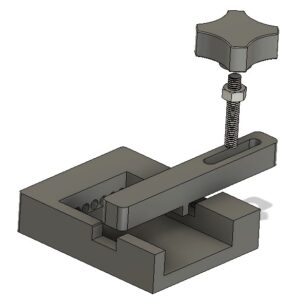
Light bulb moment – if I drilled two 6mm holes in the assembly casting opposite the two hex head screws that are holding the manifold in place, I could get a hex driver T bar to remove these screws and free the manifold from the casting wall.   This would allow the manifold to be moved to work on it.

Here is a drawing to help locate the two holes giving the distance from the back and bottom of the casting. (The lower black and blue assembly is my fogbuster mounting).

Once the manifold is free to be moved around it is possible to remove the right hand feed pipe and remove the associated length of pipework to clean it.   I found the manifold end of the pipe had not been cleanly cut and was restricting oil flow.

A word of warning – the oil feed to the ball screw is a semi rigid pipe and this terminates in the side of the ball screw.   Do not overstress this length of pipework or there will be tears.

Assembly is the reverse process.   Apologies once again for the lack of supporting pictures.

I can report my right hand side Z axis slideway oil flow is much improved.

Similar or related subjects : –

Adapter plate for a Tormach microARC to mount a Xin Dian centralising vice

I’ve made mention in another post of the arrival of the Tormach microARC to use on my Tormach PCNC440 CNC milling machine.   The microARC provides a 4th axis facility.

To date I have used this with the supplied chuck but there have been a couple of instances where a vice style stock mounting would have been useful.  I am indebted to David Loomes for bringing the Xin Dian centralising vice to my attention. 

Xin Dian centralising machine vice
The Xin Dian centralising machine vice

This is available from various sources on the Internet and at a delivered price of less than GBP100.   It is a lovely little vice.   It is supplied with an industry standard backing plate which is held in place with four M6 cap head screws.  The supplied backing plate is not suitable for mounting on the microARC .

A 3D model of the microARC is available as a Fusion file and this with some careful measurement allowed me to model a mounting plate for the Xin Dian to fit onto the microARC face.

As a secondary activity I edited the Fusion file to provide a simple sub-mounting plate for the Xin Dian vice on my PCNC440 tooling plate.

Details of both these mounting plates are contained in the PDF link below.

xin dian vice mounting plates

Similar or related subjects : –

Deburring techniques in the home workshop

I don’t know about you but deburring a job after machining I find to be a real pain.  This is an important process not just for the look of the finished product but also to give personal protection from the resulting post machining sharp edges.

If it is a CNC job then a small deburring chamfer can be added to the CAM operations but that may not be always possible to easily implement.

A manual deburrer such as made by Noga is another option but on a large geometry job it is difficult to get a uniform profile to the edge chamfers when done with such a manual tool.   Inevitably you occasionally slip and scar the surface of the job and this really irritates.

Noga Deburring Set
Noga Deburring Set with internal and external cone tools

I do like the cone shaped tool for deburring holes. Incidentally Banggood offer blades and handles that are identical and interchangeable with the Noga range including a series of different sizes of the cone tools.  Here are a couple of links to get you in the right direction but there are numerous sources of similar products.

Noga Sp1010 7 Pc 5 Application Trouble Shooter Deburring Set

Banggood DrillPro Equivalent Set

My most recent revelation was to get a deburring wheel.   I bought this from Zoro Tools.   It is a 6″ diameter wheel made by Bibielle.  There are quite a few other sources of this type of wheel. I made an arbor to mount the wheel into my drill press.  Deburring wheels are meant to be mounted on a horizontal grinding machine but bench space is tight in my workshop so it has to be a drill press mount as and when needed.  I have to say this is a joy to use and gives a quick clean finish to all cut edges.   The wheel also gets used for surface cleaning on dirty materials.   A useful addition to the workshop and one I wish I had discovered sooner.

Similar or related subjects : –

3D printed multiple punch holding tool using Fusion 360 Parameters

Using Fusion 360 Parameter Functions on this useful tool

I was pointed to this punch holder idea by a friend.  It was shown on HomeMadeTools.net and conceived by Andy Foale.   

Here is the link to the original post : –

https://www.homemadetools.net/forum/multiple-hand-stamp-helping-hand-65882

I thought it might be practical to make it as a 3D printed device and with a bit of guesswork came up with a first pass design in Fusion 360.   This was based on my set of punches which are 6.4mm square (1/4″) and 58mm long.   The design printed in PLA without any problems and the finished punch holder worked fine.  It uses one of my printed knobs as mentioned in another post.

3D printed punch holder per Andy Foales
Fusion 360 pictorial view of the finished punch holder

The success led to requests from others who liked the 3D print concept but had different size punches so needed the design tweaked to suit.

This looked like a good excuse to re-familiarise myself with Fusion 360s Parameter functions.   In short these allow you to program interrelated dimensions in a design through a series of basic algebraic functions.   The end result is a design that is fully flexible on the size of the punches to be used and the number of punches that might be judged needed as the maximum ‘word’ length.

The Fusion file is here in a ZIP file

punch holder v5

The Fusion file includes the holder, the clamping bar and the knob body.   You will need a short length of M6 threaded rod and a M6 nut to finish the knob.  The file is configured to 6mm punches, 63mm long but you can edit using Parameters function under Modify.  Clearly once you have the Fusion file you could run also run a CAM program and CNC cut the punch holder.

I am afraid this is a Fusion 360 file only.   If you aren’t a Fusion user (why not ??) and you want a STEP file creating to your punch sizes then email me and I can run it for you.

As stated in the original article, the kerning of the letters is defined by the punch cross section.

Similar or related subjects : –

Home made knobs without knurling

I always used to make customised knobs in metal which had a knurled body with a piece of studding screwed and Loctited in place.   It was good knurling practice and they looked fine until 3D printing came along.

I now have a variety of ‘styles’ for knob bodies modelled in Fusion 360.  These have a hexagonal profile recess together with either a threaded hole or  clearance hole modelled into them.   A nut is Loctited onto the thread and then the thread with the nut in place SuperGlued into the 3D printed body.

As usual I’m all for an easy (a.k.a. lazy) way of doing things …. here is a Fusion image.

3D printed knob
Fusion modelled image of a 3D printed knob

Similar or related subjects : –

Verified by ExactMetrics