Converting a vernier to a height gauge using 3D printed parts.

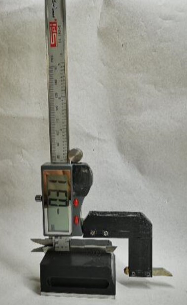
Maybe not the full shilling but functional

This concept was passed to me from a friend and is based on a design published by Ralph Patterson in 2007.   The idea was to make a mounting block and extension arm in metal to allow a vernier to ‘stand up’ and be used vertically.   My contact sent me the drawings.  I don’t seem able to find any link to this or other files by Mr Patterson.

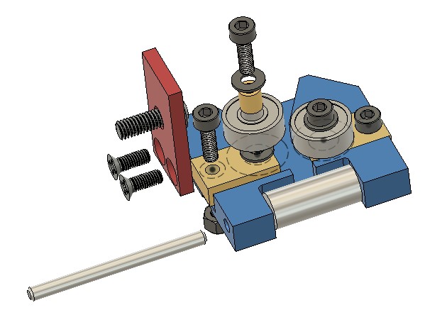
Entering the design into Fusion 360 did not take very long which indicates how well it was drawn originally by Mr Patterson.   There was one major modification however.   The original design was made from metal but our spin on it was to use 3D printed parts.   The base would therefore not have any really mass to keep it stable.   My friend suggested we added ballast in the form of lead shot into a cavity in the base.   I reduced the height of the base print by 3mm to allow an aluminium plate to be fitted to the bottom and added a honeycomb of holes into the base.   Once printed the honeycomb is filled with lead and the base screwed in place.   Conveniently and by fluke rather than design, the honeycomb holes will hold two slightly squashed 0.22″ air gun pellets.  This makes the base feel somewhat more solid on a surface plate.

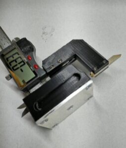
The slot in the top of the base that takes the vernier is a tight fit on two of my verniers and the third one won’t fit so care is needed in choosing the right vernier for the job.   That aside it works very well for a quick and dirty measurements.

If anyone would like the STL files then let me know on the blog email or post a comment.

Similar or related subjects : –

Lempor Nozzle added to Poly V 5″ steam locomotive

Lempor Modification to my Poly V

This post was corrupted when converting from Classic Editor to the new Block Editor and has been re-created.

I have made mention of my Poly V 5″ gauge live steam locomotive elsewhere on my blog.   With lockdown having restricted running the engine on the Club track, the loco has sat idle in the workshop.

The locomotive has always been a struggle to maintain steam over a full running day.  It starts off enthusiastically but then begins to struggle.   This is frustrating and also embarrassing when I have to push it round to the steaming bay.

I was sent some notes on Lempor Draughting to change the blast characteristics in the smoke box.  With time on my hands I spent some time on Fusion 360 drawing up a possible Lempor assembly.   This is shown below.   It consists of four nozzles each having a cumulative aperture area equal to the original blast nozzle as fitted in the Poly V.

The assembly was quite tricky. I bought in a new standard nozzle from Poly and then modelled it and the new sub nozzles in Fusion 360 to create the toolpath to mill out on the CNC, The new nozzles were created on the lathe and the mating butt flats machined on them in the mill. It was very fiddly. I wired them together and silver soldered them in place. Here is a picture of the finished assembly before fitting.

Because the new blast is diverging I had to increase the height of the petticoat. I did this experimentally by fitting a small grub screw at the back of the smoke stack to grip the petticoat as I moved it up and down. This resulted in the petticoat being almost at its maximum height. One idea suggested by a club member was to make this adjustment on a cold morning with the smoke box door open so you can see the blast pattern.

My subjective conclusion is that the engine now steams from cold much quicker and it runs very well (providing I keep the fire level high in the firebox….). Whether this is the new blast pipe or the Rosebud grate or the coal or a combination of all three is difficult to judge. It is certainly a different engine and a pleasure to drive.

Links to similar or related post are listed below : –

Burgess BK3 replacement lower blade guide

Burgess BK3 Final Modification – Lower Blade Guide

This is the final piece in my Burgess BK3 bandsaw upgrade jigsaw.   Having successfully replaced the top guide with a double bearing assembly my attention turned to the lower guide.  Using the same principle as the upper guide I came up with the following assembly.

Burgess BK3 bandsaw replacement lower guide assembly
Stylised Fusion 360 image of the replacement lower guide assembly on my Burgess BK3 bandsaw

This seems to work well and is straightforward to implement.   The bearings are standard 1/2″ size parts from Bearing Boys.   These need a small brass bush to mount them on the sliding brass blocks.  The blocks need a single M3 washer to space the bearing from the block and the body.

The blade pressure roller is made from silver steel and can be heat treated to improve wear from the blade edge.

The mounting bracket arm picks up on the original M5 mounting screw concept.  The bracket could be milled onto the main body as a CNC operation but the two part assembly works fine and is very rigid in operation.

Here is a set of drawings for my BK3 lower guide assembly

The link below is a complete set of notes and drawings pulled into one ZIP file to cover all the modifications I have done and separately document in my blog and other author’s notes that I have come across.  I hope that helps.

Updated file link to BK3 Modifications v2

Similar or related subjects : –

Verified by ExactMetrics