External battery pack to extend the battery life on wireless tags

A game of tag anyone ?

I have installed a network of low cost wireless sensor tags to monitor our homes here in the UK and also in France. These are really useful little devices that measure temperature, humidity and motion such as a door opening. 

They store their readings and can be interrogated via the Internet to see a profile history.   They also have limit alarm trip options that push messages to email to let you know if anything untoward is happening.  The product website is here.

Tag device
Image of a tag device

As examples of their use, here in the UK we have one fitted inside our freezer to check that the temperature is within limits.   Should the freezer fail or the door be left slightly ajar we get a message. 

In France we have one installed inside the spa pump cabinet to check the temperature over winter to check that the pipework does not see freezing temperatures.  This works in conjunction with a greenhouse tubular heater that is also in the spa cabinet wired to a frost stat set to 5C degrees.  If the temperature drops the pipes are protected by the heater coming on.   If the AC mains fail the heater will not come on and the sensor tag warns us to ask the neighbours to visit and check the electric distribution panel as we do experience frequent power outages.

Under normal circumstances the tag internal CR2032 battery will give a reasonable battery life approaching 12 months.  These are not normal circumstances however and due to COVID we have been unable to visit for over 12 months.  As a result all the tags at our house in France have dead batteries.  Their use inside freezers and outside in the cold degrades the battery life achieved. This got me thinking about fitting a larger battery pack to the tags in France to help longer battery life monitoring while we are absent.

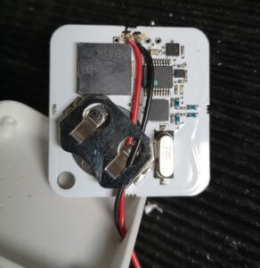
My solution is not elegant but functional.   I have wired an external battery pack containing two AA batteries to the tags.   The battery box is a commercial item and is available in packs of five on EBay.  They come fitted with an ON/OFF switch and more than enough cable to connect to the battery contacts inside the tag. 

The tag case can be sprung open with a fine screwdriver or wood chisel and the PCB removed.   The dead battery can be slid out of the PCB battery holder. There are a string of five module probing lands at the foot of the PCB and after some checking I discovered that two of these are connected to the battery holder contacts.   The external battery pack wires can be fed into the case via a 3mm hole in the top edge.   The wires then pass through the old battery holder down to the bottom of the board and are soldered in place.   The tag is re-assembled, batteries fitted and switched on.  The tag will bleep if all is well.

How to wire the external battery pack
Internal view of the tag and how to wire the external battery connections

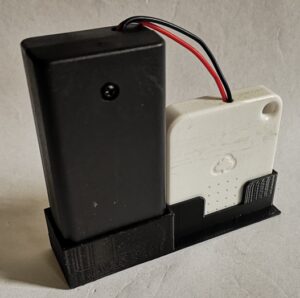
This electrical modification works but it is physically a bit gangly and scruffy.   A few minutes on Fusion 360 produced a simple 3D printed holder to contain the battery pack and the tag.   This has a slot so the temperature sensor is not obscured and a sprinkling of holes to allow physical mounting as appropriate.

Fusion 360 pictorial view of the tag and battery holder
Final assembly of the battery pack and the tag
Final assembly of the battery pack and the tag. The dot on the battery pack is a retaining screw.

In theory this modification should dramatically improve the operational life of the tags between battery changes but time will tell whether it is borne out in practice.

Similar or related subjects : –

Lockdown Pallet Beehive by Jonathan Powell

My side interest in bees brought this booklet to my attention where the author Jonathan Powell describes how he created a beehive from a couple of scrap wooden pallets.

Beehive made from scrap wooden pallets
The beehive mounted in a tree. Length is around 1m.

The hive is intended just for the bees with no intention of humans taking honey. It provides them with a tree like cavity to inhabit in keeping with a natural hole in a tree.  We humans seem to chop down our trees at an alarming rate and the potential for ancient trees with cavities suitable for wild bees diminishes by the day.

The hive has an inner core and an outer core with an insulation layer between the two using the sawdust created in cutting the pallet material.  My engineering brain kicked in and below is a spreadsheet that helps calculate the dimensions required for a multi-sided structure having the required 40 litres volume that bees appear to prefer.

Plenty of time is available to make one of these before the spring swarming period starts.

Pallet Hive Calculator

I do not claim to be an expert on bees but my interpretation is that such hives with high levels of insulation lead to less stress in the occupants.    This in turn means they are less prone to disease.   There is also much published information about the stress induced by having high density clusters of ‘domesticated’ bees leading again to disease.   Having simple well insulated hives for the wild bees to populate in relative isolation to each other must help these problems albeit at the expense of man being less able to raid honey. 

Here is an interesting link on the interaction of wild bees and domesticated bees.

For those wanting an interesting read I recommend ‘The Honeybee Democracy’ by Thomas Seeley.   Fascinating book.

Similar or related subjects : –

Vacuum table update for PCB milling

I have mentioned in the past my home made vacuum plate for holding printed circuit board material flat while milling the copper trackwork.   As a technique this works really well and the results are very consistent using 5 and 10 thou miniature milling cutters from Think and Tinker.

When the artwork design needs holes drilling through the PCB material, care has to be taken not to drill through into the aluminium surface of the vacuum table.  To protect the carbide drills and the surface of the vacuum table I use a sheet of 3mm MDF underneath the PCB material to act as a sacrificial  board .  While the MDF is ‘transparent’ to the vacuum suction it does degrade the downward vacuum grip and this has always been a frustration.   If the board does not need through holes then the MDF is not required.

My wife uses an anti-slip perforated rubber sheet on the kitchen sink draining surface.   This is very flexible and looks like a weird cobweb of holes.   It struck me that this could be used as a sacrificial sheet between the PCB material and the vacuum table surface.   The rubbery material is not perfectly flat but is very easily compressed to become consistently flat over a large area.

I begged a sheet of the material from the kitchen ‘sub stores’ and mounted it on the vacuum table with the PCB on top.   I measured the overall depth of the PCB and the mat under vacuum compression to be circa 80 thou and I usually set the depth of cut for drilling to 68 thou.  This looked like it should leave a safety margin to avoid damage to the drilling tool and the vacuum table surface.

Using anti slip rubber sheet as a sacrificial spacer
The rubber mat in place on the vacuum table

The idea worked a treat.   The PCB was very rigidly clamped  in place and no damage was done to the drill bits or the vacuum plate.  Here is an image of the first board being run using this backing material technique.

Test PCB being milled using the rubber sacrificial mat
Test PCB being milled using the rubber sacrificial mat instead of MDF

This looks like a step forward in my PCB milling process and has the added advantage that the rubber sheet can be hand washed afterwards and re-used.

Anyone needing some 3mm MDF ?

Similar or related subjects : –

Rear Parting Tool Post on Myford Super 7

 I’ve been meaning for some time to make a rear tool post for my Myford Super 7 when parting off material.   There are various comments on the web about how a rear mounted blade is the best way to succeed for this activity.

Hemmingway Kits here in the UK offer a kit of materials and instructions based on the Geo. H Thomas design as detailed in his ‘Red Book’  (ISBN 1-85761-000-8).  This seemed like a good route to take.

The kit arrived with all the materials and documentation needed including a casting for the body of the post.  You do have to make a couple of cutting tools as part of the activity but again the material is supplied for this.  I found that having access to the Red Book in conjunction with the Hemmingway kit notes helped me better understand what was involved.

Having the Tormach CNC mill allowed me to depart slightly from the intended construction  but it all came together very well.   I had some Myford Aqua blue paint to hand from my Clough42 Electronic Leadscrew control panel enclosure and this finished off the project nicely as shown below.   However I do need to crop back the excess on the rear of the blades before blood is spilt.

Hemmingway rear tool post parting tool holder
The finished rear parting tool holder made from the Hemmingway Kit

Trial cuts have so far been excellent. I can now use the power cross feed when parting brass which is a major departure.  Overall a good addition to my workshop assets and a relaxing pleasure to make.

Similar or related subjects : –

Verified by ExactMetrics