Rotring 300 2mm clutch pencil modification

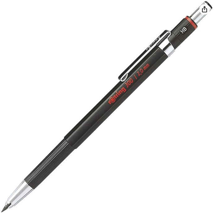
I am a great fan of the Rotring 300 clutch pencil that takes 2mm lead. Together with Sharpie markers these make good shirt pocket workshop assets. The pencil has one weakness … the useless ‘sharpener’/ lead pusher that always keeps dropping out, rolling under something/ getting lost, all of which render the pencil frustratingly useless.

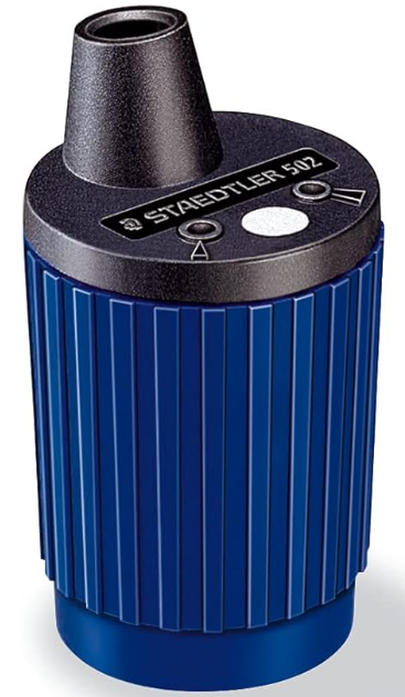
When this happens my solution is to model and make a replacement pusher albeit without the sharpener facility. I already have a Staedler Mars sharpener (#502) which is a far better sharpener.

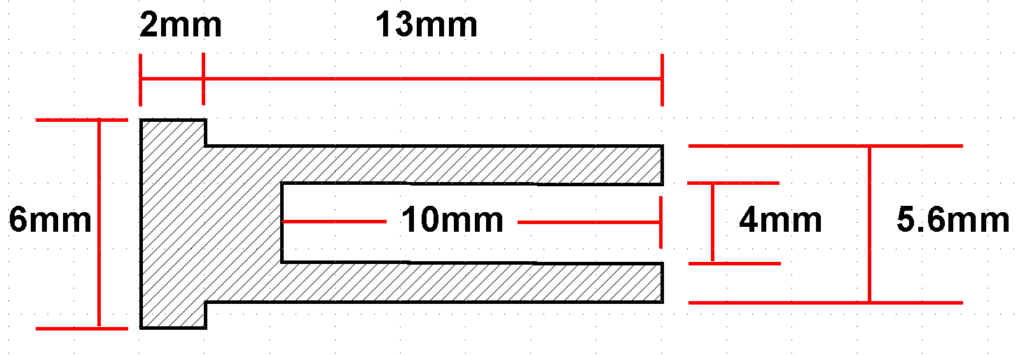
The choice of how to make the new pusher is either a very luxurious metal replacement or a cheap and easily replaceable 3D printed one. Both work well and below are the essential dimensions. Note that these are correct for a metal replacement but for a 3D printed one you might need to tweak the 4mm and 5.5mm diameters to suit your printer accuracy (4.25mm and 5.45mm on mine).

The 3D printed version has a natural friction that retains it in place. The metal one is a bit too perfect and needs the open end slightly distorted (crushed) to help retain it.

The pencils, spare leads and the sharpener all available on Amazon.

The final shirt pocket recommendation is the twin tip Sharpie marker. These are really useful for marking out.

Sorry that wasn’t very interesting but someone somewhere might be grateful of not having to waste too much time down on their knees looking for the useless end button.

Links to similar or related post are listed below : –

Qidi X Smart 3 MCU comms failure

My two Qidi X Smart 3s have been a good investment but like all things, they are only as good as their ongoing performance.

I recently had a few instances whereby my UK based printer stopped mid print having lost comms. This was the error message.

This error increased in frequency to the point where this message was present from switch on. In the process of this I learned that a good pointer to this problem is zero temperature readings on the opening LCD status screen.

Now at this point I must emphasise that in my experience Qidi support is excellent.

I opened a support dialogue with Qidi and between us we began to analyse the issue. The general initial consensus was that it was likely to be the USB-C umbilical cable connecting the motherboard to the print head. Other things that they suggested I test were whether I had too many files stored on the machine (weird one) or a hot end fan or the nozzle heater having gone short circuit both of the latter would lead to a high current demand via the USB-C. These were easy to test and checked out OK.

Focus therefore moved to the USB-C cable. This carries the power suppy to the hot end together with the control and measurement data stream between the motherboard and the hot end adapter board. The cable tested faulty (see the tester details below). To elimate whether this was the only fault I externally connected a uGreen equivalent USB-C cable but the MCU fault was still present.

The conclusion Qidi and I collectively arrived at was that there was an additional fault either with the motherboard or the adapter board.

Qidi sent me replacements items on a fast delivery from China at no cost to me. This is an example of the level of support you get from Qidi.

On receipt of the shipment it was a matter of substituting each item in turn to identify the culprit. This revealed that I had not just a faulty USB-C cable but also a faulty motherboard. The USB-C cable has to withstand a lot of flexing as the print head zooms around the chamber so I think this might have led to a fatigue related failure of the cable. I wonder also if the cable fault caused some form of knock on transient spike that damaged the motherboard.

While diving in and changing these components might seem a bit daunting, there is really no difficulty swapping them out. Remember to take a picture of everything before you commence. By far the most tricky aspect was physically removing and replacing the USB-C cable as it weaves its way round the build chamber via various slots in the cabinet.

One thing to note is that replacement motherboards, once fitted and working, may need to have their firmware updated to present issue. This is a matter of downloading the new file from the Qidi website. You have to unzip the file (a *.rar compressed file which is WinZip compatible) and then copy the file to a USB stick which you in turn plug into the printer USB port before following the onscreen instructions. Note it is important how you load the file on the memory stick in order for the auto update routine to initiate.

One outcome from all this activity is that I would recommend a USB cable tester. I bought one in from Amazon which is very analytic and immediately showed me I had a dead cable. For GBP16 this will certainly remove any future frustration caused by damaged cables.

Overall not an ideal distraction from more important projects but as ever with this type of problem, you learn more about your workshop tooling and your associated knowledge base expands.

Thank you Qidi for all your help.

Links to similar or related post are listed below : –

TPL5110 as a Monostable

After finishing a recent project I had a heap of resistors that had been used as select on test parts and now needed sorting and storing correctly. I found a design on the web for a simple Arduino based autoranging resistance meter. I prototyped the measurement circuitry for this and it worked fine. I wanted the power to the device to be from a battery source and to have this turned on via a push button switch and to auto time the ON period and return to standby.

My immediate thought was to use the ICM7555 CMOS equivalent of the ubiquitus 555 as a monostable but although manufactured in CMOS technology it does have a relatively high standby current. Some web research led me to the Texas Instruments TPL5110 which can be used as a monstable triggered from a push button. The device has an incredibly low standby current of a few uA. To use the TPL5110 as a monostable is quite simple. The EN pin is tied to ground instead of to supply. The resulting section of circuitry is simple and is shown below.

The push button sits across the U$7 (supply rail) and U$8 (trigger) terminals and the ON period of the monostable operation is adjusted by the R22 trimpot. A 10 second ON period needs around 10K. Ignore the use of parallel resistors (R21 and R18) as this was to allow my PCB layout to use either a through hole part or SMD part. The switching FET for the supply is a commonly available P channel part. The particular part chosen (DMG3416) has a very low ON resistance. Note that the TPL5110 cannot be used over 5V.

The result is very legant and simple. The standby current was so low I struggled to measure it.

Note that Adafruit has a ready made module that uses the TPL5110 but this is configured with EN permantly connected to the incoming supply. In this mode the device is intended as a timing reference to turn projects ON and OFF at regular intervals in association with feedback from an associated microcontroller (via the DONE pin). If you look at the Adafruit PCB layout you will see that you will need some delicate hacking to get at the EN pin as this is linked to the incoming supply under the TPL5110.

More will follow on the completed Resistance Meter project which has an OLED display and 3D printed enclosure.

Links to similar or related post are listed below : –

Kindling Cracker – a safer option

Four weeks ago I had an argument with my wood chopping axe. . While chopping wood against a wobbly tree stump, the stump wobbled and the axe came down on my thumb end. I didn’t feel it but it took off the tip of the bone and the severed end was only hanging on by a very thin section. My wife got me to the local A&E and a very nice paramedic cleaned and strapped things together. Since then life has been fairly miserable as I battle with buttons and being unable to do much in the workshop.

The wound is now less tender and the size of the bandage is getting less bulky. I have been warned it could take months to get any sense of feel in the tip. The problem I most stuggle with is trying to ‘unsee’ the flash back image of my thumb with its end hanging off.

In the course of recounting the incident to her golfing friends my wife was told of the Kindling Cracker. This is a wood chopping gizzmo invented in New Zealand by a young lady as a school science project . There are various YouTube videos of this device on their website. It reverses the chopping process and has the axe blade stationary with the wood being impalled in it and bashed with a club hammer. A protective ring keeps flesh away from the sharp bits.

As I have been out of action in the wood chopping department, we bought a Kindling Chopper and my wife has taken over wood chopping responsibilities. She can now split wood like a check shirted lumberjack. It is a simple but elegant design. I agree it is not as quick as chopping by hand but it needs much less effort and the chore can be delegated safely to other members of the family.

The only problem is I discovered it four weeks too late and I have got a few months left to dwell on my stupidity.

Links to similar or related post are listed below : –

Verified by ExactMetrics