3D Printed Four Facet Sharpener

A Hybrid Version of John Moran’s Elegant Design

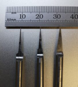
While investigating four facet drill sharpening, I came across John Moran’s website which detailed his design for a four facet drill sharpener.   Four facet sharpening is popular for providing more accurate starting of a hole, less drilling pressure, more accurate hole size and better retention of drill point sharpness. John’s design is intended for sharpening 2mm to 12mm drill bits.

I have a Quorn grinder but it is not something that I can quickly pull out from under the bench to sharpen the odd drill.   John’s design looked easy to set up and use and certainly easier to carry. I have been working with him to produce this hybrid version. I recommend that you read John’s write up before embarking on either his original design or my 3D printed hybrid version. He also presents a YouTube video on how to use the sharpener.

https://gadgetbuilder.com/DrillSharp.html#Facet4

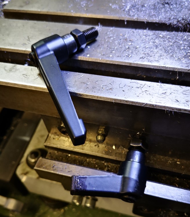
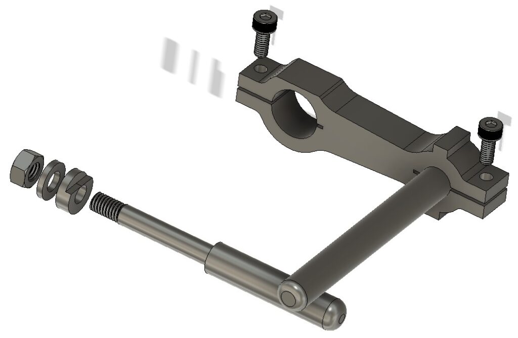
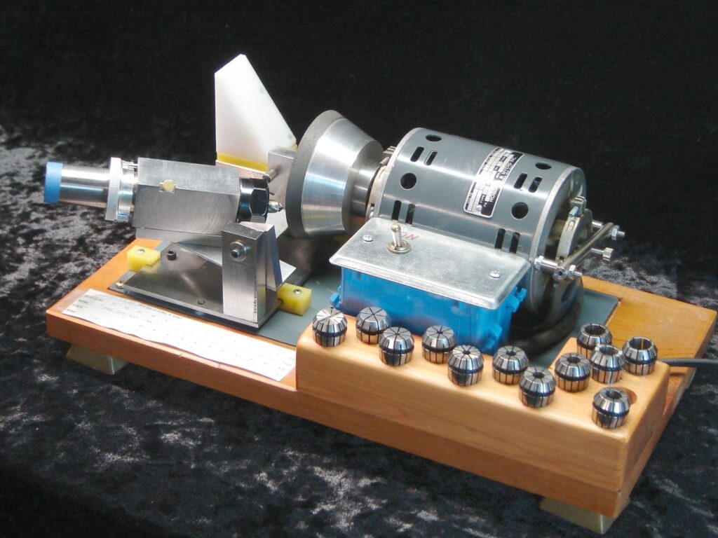
Here is a picture of John’s finished design. Very nicely finished and presented.

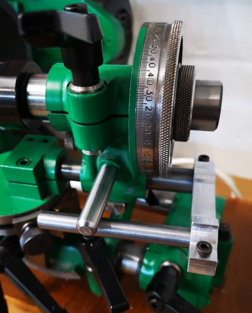
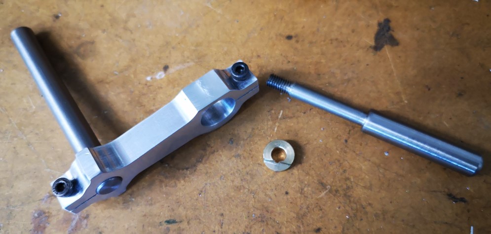
Here is a picture (not quite so pretty …) of my 3D printed hybrid version. A new baseplate might be in order to smarten it up.

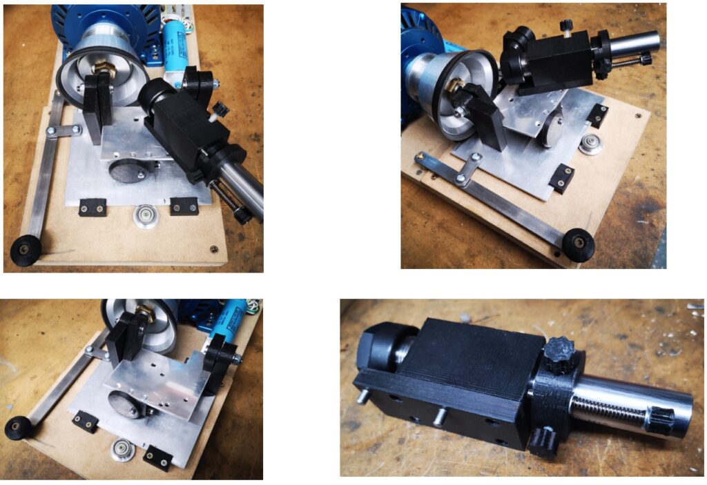
The concept of combining 3D printed components with essential metal parts works very well and the resulting sharpener appears to be stable and repeatable in its results. There is a huge advantage in combining technologies in this manner. All the ‘boring’ or ‘dreading to make / leave until tomorrow’ parts are easily produced on a 3D printer and the remaining metal parts are straightforward to produce with conventional resources and skills.

Rather than go into details as a blog post, below is a link to a ZIP file that contains my full write up, 2D PDF drawings of the metal parts, STEP files of the 3D printed files and the raw Fusion files for those wanting to tweak.

If you can’t work with STEP files then let me know and I will run STL versions. STEP files are more accurate than STLs and also have the advantage of being more easily editable than STLs.

I think you will be impressed with the end result of John’s design.

If this write up or my general waffle is of interest then please subscribe to receive notices of new posts. If you build the sharpener and it works let me know. If it doesn’t work and it’s my fault for not providing enough information than email me so I can correct things.

As an alternative to a 3D printed version you can watch Mark Presling on YouTube who has recently construct the same sharpener in metal.

UPDATE

I have already had some feedback on the 3D printed design so some of you are quick off the mark.

This feedback related to the friction of the collet holder shank in the block and also the print roughness against the depth setting screw.   Both of these will relate to the print quality from your printer.

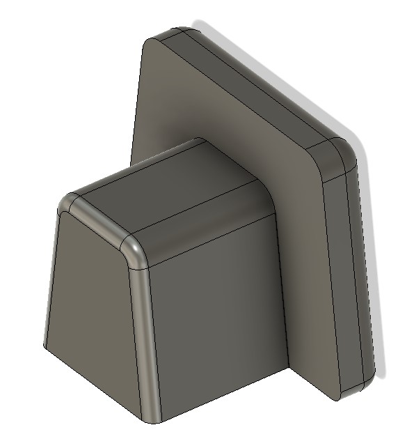
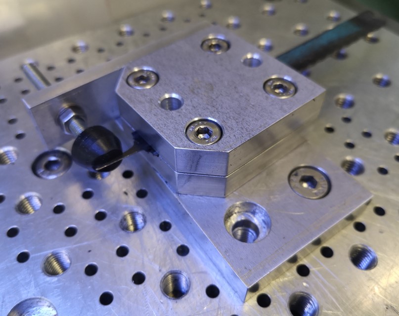
As an experiment I ran a new version of the block with a larger bore and then lined it with an aluminium sleeve that was a smooth fit on the shank.   I also turned a flange on the end of this sleeve so that the adjuster nut had a smooth metal surface to ride against.

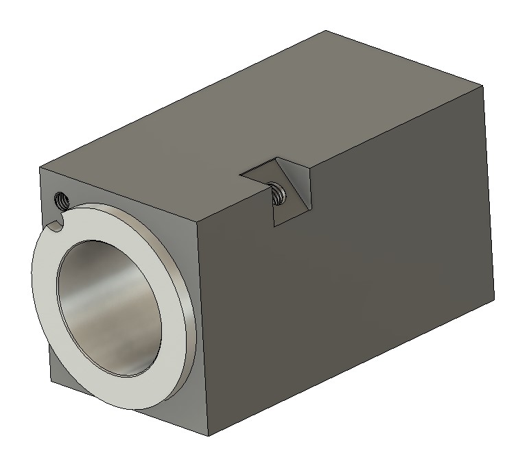
The addition of the sleeve looks promising in solving these two issues.  I admit it is going against the concept of a 3D printed set of parts but the sleeve is easy to turn up on the lathe and the new block in PLA is still much easier to produce that trying to make the block totally in metal.

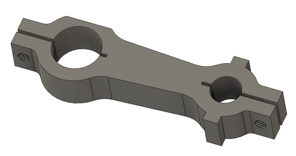
You can download the edited write up, new collet chuch holder block STEP and the sleeve drawing in this add on ZIP file.

Links to similar or related post are listed below : –

Truncated Lock Levers

Restricted space modified lock levers

Each of the axis locks on my VMB mill uses two M8 cap head screws in association with a lock nut. This works OK if the hex driver is in reach …. but it never seemed to be …. so I decided to remove the cap head screws and fit lock levers instead. Lock levers come in male and female format and various thread sizes. The M8 versions all have 40 to 50mm long lever arms. This length doesn’t work comfortably in the space constraints on the VMB X and Y axis but is fine for the Z axis. Similarly I also had to reduce the length of the lever thread.

The obvious solution was to cut down the length of the lever arms. The trouble with this was the raw open end of the arm looked naff and did not sit easily with my usual perfectionist approach. The solution via Fusion 360 was to create some 3D printed end caps which I then bonded in place with Araldite. This finished the job properly.

Fusion 360 modelled end cap for the shortened lock lever arm open end

The Fusion 360 3D modelled end cap printed in under 4 minutes with a further 5 minutes for the Araldite to cure. I now have a much more elegant looking solution.

Full length lock lever and the truncated version with 3D printed end cap mounted on my VMB mill

All of which has led to a rethink the lock levers on my Quorn tool grinder. I get in a real mess with these clashing with each other. Where did I put the Araldite ? …..

Links to similar or related post are listed below : –

Quorn cutter grinder tool holder support

I am slowly getting to understand how to manipulate and use my recently purchased Quorn tool cutter grinder.    One frustration that kept cropping up was the workhead assembly slip rotating on the bed bar. This usually happens when there is a need to slide the tool holder head back after a referencing action.  This messes up the reference setting.

I chanced upon a thread on the MEW forum where a John P had solved this problem with a parallel support bar assembly.   This utilised the 1/4″unused hole in the toolholder side wall.  There are a number of ways to fabricate this fixture but the important aspects are that it should be robust and must ensure a parallel motion along the support rod.

quorn cutter grinder tool head support bar
The cutter grinder tool head support bar mounted on my Quorn

I opted to model the bracket in Fusion 360.  As there will be little stress on the bracket in use I opted to mill it from 15mm cast aluminium to give a 12mm finishing depth.  Here is the pictorial view from the Fusion desktop.

Fusion 360 model of the Quorn cutter grinder tool head bracket
Fusion 360 model of the Quorn cutter grinder tool head bracket.  The bracket measures around 90mm end to end.

The bracket has a 5/8″ hole to match the Quorn table slider rod and a 10mm hole for the new parallel support rod (sorry about the mixed dimensions but my Quorn is an Imperial model and most of my stock is metric).   

Side #1 CAM operations are to clean up skim the stock top surface followed by profiling the two holes and the outside shape.  Side #2 is to invert the model and deck the excess material.   The clamping slots, the flat adjacent to the 5/8″ hole and the M4 tapped holes are all supressed in the CAM and manually cut post CNC operations.

The model has two tabs adjacent to the 10mm hole.  These have no relevance to the use of the bracket but are there to make the width of the model equal.  This negates the need to use soft jaws to hold the model when undertaking side 2 operations to deck off the excess stock material. The decking brings the model to 10mm finishing depth.   These two tabs could be ground off afterwards if desired. 

I did consider grub screw clamping of both bars but there was a danger of deforming the associated bars.   It was easier and more elegant to design slot clamps into the Fusion model. The clamping slits were cut post CNC machining on my BK3 bandsaw.   (Try cutting straight slots on a BK3 without a decent fence and support bearings.) The parallel nature of the finished model width as mentioned above makes this a simple process against the bandsaw fence.

The two M4 clamping screw holes are drilled prior to the slots being cut.  The holes are drilled 3.3mm through and then M4 through threaded.  After the slots are cut one half of each hole is clearance drilled to M4. 

The flat adjacent to the 5/8″ hole is the last ‘after CNC’ machining operation.  This flat gives the clearance needed to allow the bracket to slide under the Quorn toolholder referencing dial.

The gliding bar is mounted in the spare hole in the tool holder side wall.   This hole in my Quorn had been drilled 1/4″.   The rod profile was turned with a centre from 10mm silver steel to have the 1/4″ section and then a short section threaded M6.   Note that I also made a brass washer profiled to match the rear face of the through hole in the body.  Like most of the Quorn casting holes this had a step segmented surface aimed at stopping bolt head rotations.

Fusion 360 pictorial view of the assembly
Quorn cutter grinder tool head support components
Quorn cutter grinder tool head support components – this shows the bracket with support bar in place, supporting rod and profiled washer.

Mounted on the Quorn, the assembly sat nicely parallel, is very solid and stable and does an excellent job of stopping the head drooping.  My frustrations over this aspect of the Quorn are eased for the time being.

If any readers want the Fusion file or dimensioned drawings then add a comment below.

UPDATE : – The bracket should be rigid enough when 3D printed instead of machined from solid. Here is a ZIP file containing  the support bar clamp version v5 as a STEP file.  All the other parts are straightforward lathe operations.

Similar or related subjects : –

Quorn grinder and locomotive injectors

I picked up a Mk1 Quorn Grinder, that is to say I bought one second hand.. not used one as part of my (lack of) exercise regime … it is very heavy.   It did not have a drive belt nor any tooling but otherwise is in good condition and very well made.  I believe the construction was done by the now departed Derek Collier of Bristol and I am very pleased to become the custodian of this fine piece of workmanship.

The belt was easily sourced through the ever helpful Tony at lathes.co.uk and a 5mm x 600mm belt arrived by post a couple of days later.   The Quorn motor now spins the grinding cone so some small progress.

Hemmingway Kits offer a Mk3 version of their Quorn kit and I bought just the drawings from them as a reference document to partner the original Professor DH Chaddock book that came with my machine.  One of the key differences of the MK3 is the decision to use a 25mm diameter ER collet chuck as the work holding mechanism.   This replaces the original 1″ diameter tooling jig.   Clearly for a new build this diameter is easy to plan for and to source a mating 25mm ER collet extension.  Not so easy is a retrospective replacement for the 1″ original jig.   After some help from John Saunders at NYC CNC I sourced a 1″ diameter ER extension from Maritool in the US.  Maritool offer both ER25 and ER32 sizes in various lengths.   Buying direct from the US means paying a similar price for the shipping as for the collet. (Time to call in some favours from relations living in the US ?) Until this turns up I will be spending time trying to work out how to use the Quorn. 

The second background activity here is trying to make an injector for my 5″ Poly V live steam locomotive.   Building a Quorn from scratch and also making an injector seem to be rights of passage activities for any home workshop.  Clearly I have copped out on the former and I admit to struggling with the latter.

I am working from DAG Brown’s book and so far I have made the injector body parts and I have made the 6/9/13 degree D bit reamers.   The reamers were hardened and tempered today using my Prometheus oven.   The accuracy of the oven controller makes this process much easier than hit and miss heating with a gas torch.   Partial red green colour blindness does not sit well while trying to watch temperature colour changes.  Here are the completed reamers before heat treatment.

6/9/13 included angle D bit reamers for injector cone angles
6/9/13 included angle D bit reamers for injector cone reaming

I use Ground Flat Stock’s ATP-641 to protect the silver steel from scaling during heat treatment.  This works very well.   ATP-641 is a water based grey sludge that you dunk the object in and allow to dry in air.  It is essential that you thoroughly degrease the parts first as being water based the sludge ‘runs back’ from grease and does not cover the object as a result.   It is also important to make sure the sludge is thoroughly dry before putting the objects into the oven.  It does chip off easily so care is needed. I usually heat silver steel objects to 500 degrees and hold for an hour and then increase to 800 degrees and hold for another hour (depending on the mass of the object).    Once quenched the grey sludge protective shell just cracks away leaving a dull grey but clean surface on the object.  ATP-641 is excellent to use and helps takes the human variables out of the process.

Back to the D bit reamers … there have been a series of articles on injectors in the last four Model Engineer magazines.   In one of these articles it was mentioned that reamers could be made from hacksaw blades.   Always keen for an easy life I made a jig for doing this which would hold the hacksaw blade to allow it to be ground to size using a Dremel grinding bit (#457).   This concept worked incredibly well BUT the thickness of the hacksaw blade makes this method only suitable for 32oz injectors and above.  Below this size the blade interferes with the miniature holes in the cone jets.  D bits therefore rule for the smaller versions.  Here is the hacksaw jig with an added antivibration rubber button.  The top two blocks clamp the blade and these rotate on the lower base plate to set the angle.   The blade is flipped over in the clamp to allow grinding on each side.  The grinding is always along the X axis of the mill.

Jig for grinding a hacksaw blade to make a taper reamer for making live steam injector cones,
Jig for grinding a hacksaw blade to make a taper reamer for making live steam injector cones,  The jig sits on my CNC mill tooling plate to correctly set the X axis of the grinding motion.

Lots of links in the text today and I have no allegiance with any of the entities mentioned.  Updates of progress and a full write up will no doubt follow …

Similar or related subjects : –

Verified by ExactMetrics