How sad is this ?
I recently bought an Imperial set of ER25 collets to compliment my metric versions. I also have a set of metric ER20 and ER11. They have all been delivered in little yellow boxes which is good from a shipping point of view but a faff when needing to use them. In the past I have made storage blocks using odd pieces of wood with tapered holes cut using a cone cut drill bit. The cone cut has a 6 degree taper and ER collets all have 8 degrees so it sort of works but not quite ideal for my perfectionist mind.
As ever, the 3D printer sits in the corner begging to be used and Fusion 360 challenges me to do something a bit more professional. The scene is set for an overengineered collet storage tray.
Now I could just model and print something to hold the twelve new Imperial size delivery but what if I add to them at a later date? What if I decide to get some ER20 Imperial versions also ? ……….. Could I create a Fusion based automated model that will cope with any sized matrix of holes and any size of collet?
The first exploratory step was to create an Excel spreadsheet (another of my fascinations) as a means of identifying the steps that might be involved in automating the design and to tabulate the different parameters of the various ER series collets. Here is a screen shot.

A little bit more detail will be needed for you to understand what this all means.
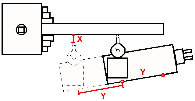
The top table just details the published specification dimensions of the ER range of collets. I needed the height of the tapered section and this is calculated. Note that not all collets have the parallel section at the top of the taper. If you extrapolate the taper it then coincides with the dimension D1 and this is one I have used in the calculations.
Each collet holder hole in the block will be an 8 degree tapered hole that the collet sits in such that it does not sit all the way through the block (I opted for a 1mm bottom gap) and such that a percentage of its height protrudes from the top of the hole (I opted for 30%). The middle right hand sketch shows the various parameters and the red outline represents the collet.
The lower table shows the set up for the model parameters with spacing and borders defined. This section allows entry of the all important ‘how many holes do I want’ and the aspect ratio of the matrix. The final two red lines shows how big the resulting storage block will be.
All with it so far ? This is so embarrassingly sad … should I even be thinking of posting it…
These various parameters are now mirrored and entered in Fusion 360’s Fx parameter set up. I have tried to be logical in the naming convention and the blue stars indicate a function that is defined and entered by the user and will also appear in parallel in the Fx Favourites listing. This allows a focussed entry of just the variable parameters without all the other background calculation clutter.
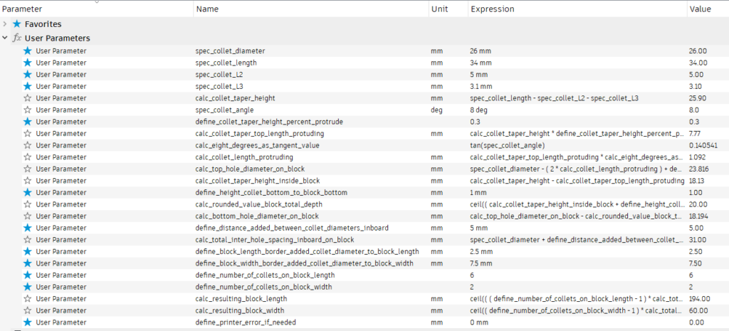
I wanted to round the resulting block size to a nearest whole number. My preferred function in Excel is “mRound” where you can define the rounding to an increment value. There is no such equivalent in Fusion. In the end I used the “Ceil” in Fusion and “Ceiling” in Excel but Excel’s “Ceiling” requires a ’rounding to value’ hence the entry line (R) in the Excel listing which is set to ‘1’ to make it match the Fusion calculations.
By setting the length and width hole count to ‘1’ a single holder can be printed and checked to dimension before doing a full matrix as needed. I found that on my first single hole print the collet sat slightly higher in the hole than designed but this was traced to a print artefact on the taper wall. This was was easily rubbed down. On similar tack, I have allowed a fudge factor for print shrinkage should this be needed. Any errors in this respect will cause the collet to sit higher on the block. This will be most apparent as the collet size reduces. The value entered (say 0.1mm) adds a linear amount to the top and bottom hole sizes and therefore the taper.
Once you are happy with the single hole print you can define the number and aspect ratio of how you want the holes to be printed on the finished block. A 6 x 2 print will match the normal 12 piece ER25 collet set. On the Qidi ifast printer this took around 4 hours at 0.25mm layer height. Note that I used the ‘Shell’ command on the block lower surface of the print to reduce material use. This means you need to place on the printer bed ‘bottom side up’.
Well I did say this was going to be a sad nerdy post but as ever I learned a bit more about Fusion, Excel, refreshed my school geometry and made the workshop even more tidy and organised. What’s not to like ? …..
While this is an almost facetious waste of time and effort, the principles used in the Fx programming has many other applications.
The planning spreadsheet has been added to my spreadsheet compendium which along with the Fusion file (for ER25) is attached on the following ZIP file link.
Links to similar or related post are listed below : –
- Fusion Electronics Library Notes and Crib Sheet
- I had a ChatGPT experience
- Fusion Sheet Metal model export as PDF
- Drawing a parabola in Fusion
- Creating Customised Threads in Fusion 360
- Automated 3D printed collet storage using Fusion 360 parameters
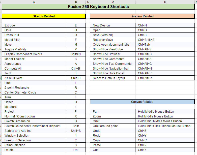
- Fusion 360 Keyboard Shortcuts
- Creating a worm drive in Fusion 360
- Fusion 360 Parameter Lookup Sheet
- Adding Colour Coding to Fusion 360 Assemblies