Tormach MicroArc and Fusion 360 and 4th Axis

Tormach MicroArc 4th Axis Arrives

At last a 4th axis drive for the Tormach PCNC440 ! 

tormach microarc 4th axis

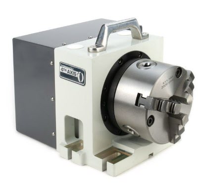
I have waited 4 years for this to be available and did not hesitate to put in my order to Tormach for one of the new MicroArc drives.  Probably the best way to get a good idea of this product is to watch John Saunders’ video.

The MicroArc wasn’t a low cost buy and because 4th axis was not around when my 440 was originally shipped, I needed a fitting upgrade kit as part of the order.   Having placed my order with Tormach it took exactly 7 days for DHL to arrive on my doorstep with the shipment.  Quite amazing considering the difficult times we are experiencing at the moment.

It took me about one hour to fit the new stepper driver and additional wiring.  As ever there were good clear instructions from Tormach.   I switched on the 440, enabled the 4th axis in PathPilot and I could control the A axis from the PathPilot screen.   Very impressed.

I watched John Saunders video on the MicroArc and how to do 4th axis programming in Fusion 360.  I drew up a simple model in Fusion but could not get it to produce working GCode.  I had some comms with John and he gave me some pointers.   The model had a rotational repeat pattern but while I could run a single op code, if I tried to run the rotational pattern the post processor came up with an error message and would not output any code.

I thought at first it was because I was only using a Fusion hobbyist licence and that 4th axis maybe was not possible.   A really helpful dialogue with Shannon McGarry at Fusion cleared up that issue so it must be something else.

After some experimenting I discovered that you have to set the axis of rotation in the post processor dialogue options list.   All then worked fine. 

We are up and running on 4th axis !

Similar or related subjects : –

Replacement Chuck Key for a Cowells ME Lathe

Broken Tooth and No Dentist ?

The Cowells Model Engineer miniature lathe is very popular in home workshops.   It is a well made machine and very accurate to use.

There appears to be one recurring problem with the design and that is the chuck key for the TMC3001 3 jaw chuck often ends up with broken teeth.   To understand this better you need to be aware that the Cowells chuck does not have a standard style chuck key.    It is more like a drill press chuck key as you will see from the image below.  It also has 12 teeth which is unusual compared with drill press chuck keys which usually have 11 teeth. Using too much strength trying to over tighten the chuck rotary mechanism could lead to severe machinist depression.

cowells 3 jaw chuck and chuck key
Cowells 3 jaw chuck and chuck key

I have to admit this is going to be another JSN job that slipped through the net while the sign had been left facing the wall from the last one …. a client wanted to know if I could make a replacement chuck key. 

It seems that these are not readily available as replacement parts.  So another little challenge was beginning to niggle at me. I thought about try to use Fusion  360 to create CAM for my Tormach PCNC440 CNC mill it but it didn’t feel like the right approach.  There had to be an easier way.   

While siting in the sunshine at lunch time (probably not paying attention to what my wife was telling me …. (again) …. ) I wondered if standard wheel cutting techniques could be used.   This would mean a custom made fly cutter which didn’t fill me with joy and suggested a lot of grief.  I then wondered if a standard clock wheel cutter might fit the same profile as the chuck key teeth.

With lunch over I dug out my treasure trove of PP Thornton wheel cutters and compared them with the profile of the chuck key.   The PP Thornton 0.95-7 modulus one looked a good bet as a match.   In its normal life this would be a 7 tooth pinion cutter. 

The idea looked like it might work.  I measured and sketched up the rough dimensions of the chuck key head profile which is shown below.   For ease of making a proof of concept prototype I decided to use aluminium.

First job was to profile the aluminium stock to the outline shape of the chuck key.  This completed I then mounted my Sherline CNC rotary table in the mill table vice and with some jiggery pokery managed to get the vice / table aligned at 14 degrees (90-76) to the X axis movement.   I set the centre line of the pinion cutter with the centre line of the aluminium profile.  I dialled in 12 steps on the Sherline and began cutting back and forth.   

To match the original teeth depth I had to go down to the full depth of what the pinion  cutter profile would allow.  On the prototype I didn’t bother finishing the shank of the key and below are some process images and the final prototype result.

process shots of making a cowells chuck key replacement and resulting piece
Images of the process and final result making a prototype Cowells lathe chuck key replacement.

The prototype worked.  I just have to make a fully finished steel version …… oh and remember to turn the JSN notice back over so I can’t miss seeing it next time an intriguing enquiry comes in.

Update : –  Silver steel ruined my cutter … they are really meant for brass. Looks like it will have to be a CNC method.

Similar or related subjects : –

Making a Brocot Escape Wheel using Fusion 360 and Tormach PCNC440 CNC milling machine

A Steep Learning Curve

My wife has presented me with a sign that has just got JSN written on it.  It is to remind me when I answer the phone to a ‘can you just do’ enquiry…… to Just Say No.

I try my best to live up to her expectations but sometimes something comes along that should really be a JSN job but which scratches an itch.   You know what I mean.   You think about it and you do all the right mental arithmetic in your head and the answer keeps coming back to the same – don’t even think about it.  But the the other side of my brain is screaming at me … what a challenge, what a learning experience, what fun to have a go at it.   Providing the asking party is aware of your thought process or lack of it and accepts that it might just go belly up and never come to fruition then why not ?

Back to the story – 10 days or so ago I had a call from David Pawley who is a turret clock expert extraordinaire to say someone he knew was after an escape wheel for a turret clock and was desperate.   David passed on the details and a couple of days later the potential customer arrived on our driveway.  After a suitably socially distant conversation and a rubber gloves inspection of the old damaged wheel …. I got sucked in and turned the JSN sign over to face the wall.

Brocot 30 tooth escape wheel
The original Brocot 30 tooth escape wheel that needed a new one making

As you can see it is not an ordinary escape wheel and I had to delve into one of my favourite books ‘Wheel and Pinion Cutting in Horology’ by J Malcolm Wild FBHI in order to learn about Brocot Escape wheels.   Malcolm is a great guy and his book should be on any clock experimenters bookcase.

The Brocot is no ordinary escape wheel.   In fact it is a real challenge.   Not a simple fly cutter job.  Traditionally it would be cut in an indexing device such as a lathe with two different cutters, one for the curve and one for the notch.  I didn’t have these so I thought I would probably upset the traditionalists and try to use CNC.

Read all about the adventure and see the result in this pdf download …….

Similar or related subjects : –

Experiences and understanding FlatCAM PCB milling program

FlatCAM Write Up – Experiences and Procedures

After a lot of editing I think the attached document will give an in depth understanding of how to use FlatCAM based on Version 8.5.   The document is based on our experiences and a steep learning curve.  We now have a repeatable process for milling PCBs from Gerber and Excellon files exported from a PCB design package.

The document may well have mistakes and we would appreciate feedback good or bad.

Latest version is now based on FlatCAM v8.991

FlatCAM v8.991 and milling pcbs 2021

Similar or related subjects : –

Supply, IC2 and USB connections over CAT5 connection

CAT5 Breakout Board

One of our group of ‘silver experimenters’ is building an Arduino based celestial camera tracker.   This will be deployed in the garden and he needed all control to be routed back inside the house.   The garden installation consists of a USB webcam mounted on a servo controlled platform all powered by 12V DC.

We pondered long on how we might remotely connect to the garden.  The crucial thought was that the Arduino servo board was a two wire interface using the I2C format data exchange.   Given that the USB needed four wires and the DC supply two wires we had a need for an eight core cable connection.  It seemed like a length of CAT5 cable would do the job and we could elegantly use standard CAT5 sockets.

The PCB was designed in Design Spark and milled on the Tormach PCNC440 using FlatCAM.

There is a problem with running USB over more than 5m but I did some tests at 10m and all seemed fine which should be adequate for the application.   

The breakout boards had a male and female USB connector fitted and the connections had to ‘cross over’ on one of the breakout boards to maintain continuity.   We also paired the Data + and Data – connections with the +5 and Ground twisted pairs in the CAT5 so the Data + and Data – were not twinned together.

Nothing technically magic but a simple solution to a project need.

CAT5 breakout board for USB, I2C and DC supply
CAT5 breakout boards for USB, I2C and DC supply

  Similar or related subjects : –

Verified by ExactMetrics